Homework #8 Solutions
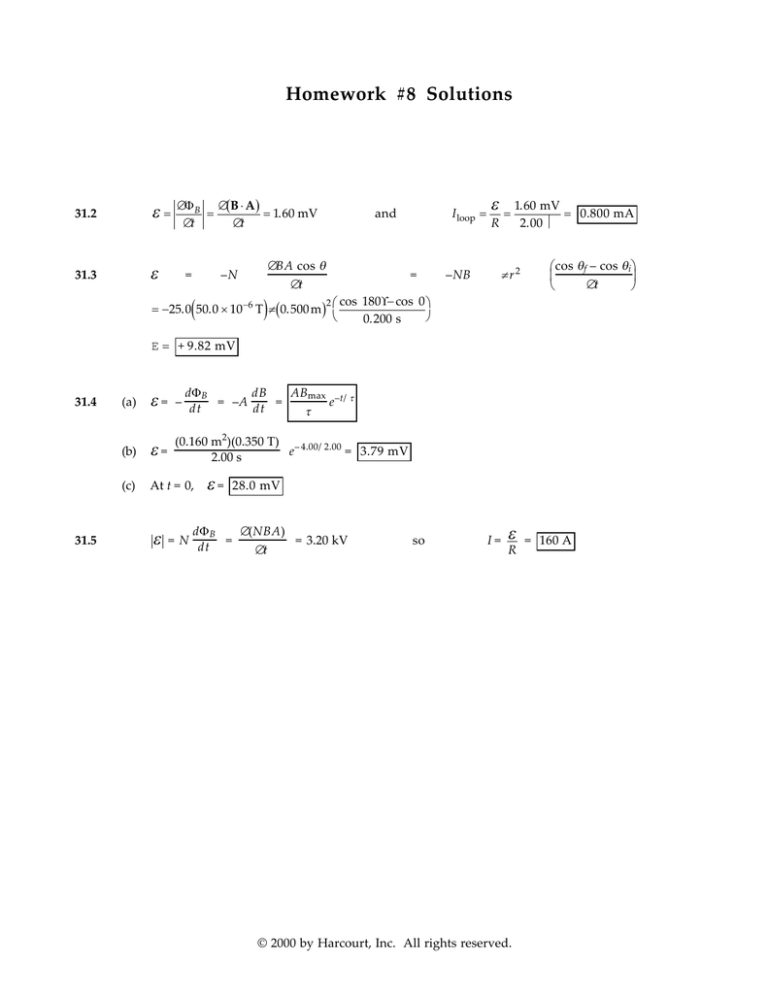
31.2
ε=
31.3
ε
∆Φ B ∆(B ⋅ A )
=
= 1.60 mV
∆t
∆t
=
–N
(
∆BA cos θ
=
∆t
)
= −25.0 50.0 × 10 −6 T π (0.500 m )
I loop =
and
2 cos
–NB
ε
=
R
1.60 mV
= 0.800 mA
2.00 Ω
πr2
180° − cos 0
0.200 s
cos θf – cos θi
∆t
E = + 9.82 mV
31.4
31.5
(a)
ε=
dΦB
dB
ABmax –t/ τ
– dt = –A dt =
e
τ
(b)
ε=
(0.160 m2)(0.350 T) – 4.00/2.00
e
= 3.79 mV
2.00 s
(c)
At t = 0,
ε
ε=
28.0 mV
dΦ B
∆(NBA)
= N dt =
= 3.20 kV
∆t
so
I=
ε
R
© 2000 by Harcourt, Inc. All rights reserved.
= 160 A
220 Chapter 31 Solutions
ε
2
µ 0 n π r 2 ∆I
2R ∆t
(a)
Iring =
(b)
µ 0 n π r2 ∆I
µ 0I
B = 2r = 4r R
1
1
∆t
(c)
The coil's field points downward, and is increasing, so
(a)
dΦ B = B ⋅ dA =
(b)
ε=
R
=
2
31.9
−
2
µ0I
Ldx :
2π x
ΦB = ∫
h+w µ 0 IL
x=h
2π
Bring points upward .
µ IL h + w
dx
= 0 ln
h
2π
x
dΦ B
d µ IL h + w
µ L h + w dI
= − 0 ln
= − 0 ln
dt 2 π
h
dt
2 π h dt
4 π × 10
ε = −(
−7
)
T ⋅ m A (1.00 m )
2π
ln
A
1.00 + 10.0
10.0
=
s
1.00
− 4.80 µ V
The long wire produces magnetic flux into the page through the rectangle (first figure, above).
As it increases, the rectangle wants to produce its own magnetic field out of the page, which it
does by carrying counterclockwise current (second figure, above).
224 Chapter 31 Solutions
In a toroid, all the flux is confined to the inside of
the toroid.
31.17
B=
µ 0 NI 500 µ 0 I
=
2π r
2π r
Φ B = ∫ B dA =
ΦB =
500 µ 0 I max
dz dr
sin ω t ∫
2π
r
500 µ 0 I max
b + R
asin ω t ln
R
2π
ε = N ′ dΦB = 20 500 µ 0 Imax ω a ln b + R cos ω t
dt
2π
R
rad
N
( 3.00 + 4.00) cm
4 π × 10 −7 2 ( 50.0 A ) 377
(0.0200 m)ln
cos ω t = (0.422 V) cos ω t
s
2π
4.00 cm
A
ε = 10
31.18
4
N
I
l
The field inside the solenoid is:
B = µ 0nI = µ 0
Thus, through the single-turn loop
Φ B = BAsolenoid = µ 0
and the induced emf in the loop is
ε = − ∆ΦB = −µ 0 N (π r 2 ) ∆I =
ε = −N dΦB
31.19
IR = −N
dt
Idt = −
Q=−
N
dΦ B
R
∆t
dΦ B
dt
N
∫ Idt = − R ∫ dΦB
(
N
N
∆Φ B = − A Bf − Bi
R
R
)
200
−4
2
Q = −
(100 × 10 m )(−1.10 − 1.10) T = 0.880 C
5.00 Ω
31.20
I=
ε
R
=
Blv
R
v = 1.00 m/s
l
( )
N
π r2 I
l
∆t
−
µ 0 Nπ r 2 I 2 – I1
∆t
l
Chapter 31 Solutions 225
31.21
(a)
F B = I 1 × B = I lB.
FB =
When I = E / R and
ε = Blv , we get
Blv
B2l2 v (2.50)2 (1.20)2 (2.00)
(lB) =
=
= 3.00 N
R
6.00
R
The applied force is 3.00 N to the right
(b)
P = I 2R =
FB = IlB
*31.22
I=
31.23
B2l2 v 2
= 6.00 W
R
E Blv
=
R
R
I 2lR
lv
(a)
FB =
(b)
I 2R = 2.00 W
(c)
For constant force,
or P = Fv = 6.00 W
and
E = Blv
so
B=
and
I=
IR
lv
FB v
= 0.500 A
R
P = F ⋅ v = (1.00 N )( 2.00 m / s) = 2.00 W
The downward component of B, perpendicular to v, is (50.0 × 10⁻⁶ T) sin 58.0° = 4.24 × 10⁻⁵ T
(
)
E = Blv = 4.24 × 10 −5 T (60.0 m )( 300 m / s) = 0.763 V
The left wing tip is positive relative to the right.
31.24
d
ε = –N dt
∆A
BA cos θ = –NB cos θ
∆t
ε = –1(0.100 T) cos 0°
I=
(3.00 m × 3.00 m sin 60.0°) – (3.00 m)2
= 1.21 V
0.100 s
1.21 V
= 0.121 A
10.0 Ω
The flux is into the page and decreasing. The loop makes its
own magnetic field into the page by carrying clockwise
current.
31.25
ω = (2.00 rev/s)(2π rad/rev) = (4.00)π rad/s
1
2
E = Bω l2 = 2.83 mV
© 2000 by Harcourt, Inc. All rights reserved.
226 Chapter 31 Solutions
31.26
(a)
Bext = Bext i and Bext decreases; therefore, the induced
field is B0 = B 0 i (to the right). Therefore, the current
is to the right in the resistor.
(b)
Bext = Bext (–i) increases; therefore, the induced field
B0 = B 0 (+ i) is to the right, and the current is
to the right in the resistor.
(c)
(a)
(b)
(c)
(d)
Bext = Bext (–k) into the paper and Bext decreases;
therefore, the induced field is B0 = B 0 (–k) into the
paper. Therefore, the current is to the right in the
resistor.
(d) By the Lorentz force law, F B = q (v × B). Therefore, a
positive charge will move to the top of the bar if B is
into the paper .
31.27
(a)
The force on the side of the coil entering the field
(consisting of N wires) is
F = N ( ILB) = N ( IwB)
The induced emf in the coil is
ε
=N
d(Bwx )
dΦ B
=N
= NBwv,
dt
dt
so the current is I =
ε
R
=
NBwv
R
counterclockwise.
The force on the leading side of the coil is then:
F=N
N 2B2 w 2 v
NBwv
wB =
to the left
R
R
Φ B = NBA = constant , so
ε = 0,
(b)
Once the coil is entirely inside the field,
.
I = 0,
and F = 0
(c)
As the coil starts to leave the field, the flux decreases at the rate Bwv , so the magnitude of the
current is the same as in part (a), but now the current flows clockwise. Thus, the force exerted
on the trailing side of the coil is:
238 Chapter 31 Solutions
*31.58 (a)
dq
ε
I = dt =
R
E = −N
where
dΦ B
dt
so
and the charge through the circuit will be
(b)
31.59
31.60
N
π BAN
=
BA cos 0 − BA cos
2
R
R
so
B=
RQ
NA
=
(200 Ω)(5.00 × 10– 4 C)
(100)(40.0 × 10– 4 m 2 )
ε
Q
=
N
R
Φ2
∫ dΦB
Φ1
N
(Φ2 – Φ1)
R
= 0.250 T
(a)
ε = B lv = 0.360 V
(b)
FB = IlB = 0.108 N
(c)
Since the magnetic flux B · A is in effect decreasing, the
induced current flow through R is from b to a. Point b is at
higher potential.
(d)
N o . Magnetic flux will increase through a loop to the left of ab. Here counterclockwise
current will flow to produce upward magnetic field. The in R is still from b to a.
I=
R
= 0.900 A
ε = Blv at a distance r from wire
ε
31.61
Q=
∫ dq =
(a)
µ I
= 0 lv
2π r
At time t , the flux through the loop is
At t = 0, Φ B = π ar 2
(b)
ε = − dΦB = − π r 2 d( a + bt) =
(c)
I=
(d)
π br 2
π 2b 2 r 4
2
P = ε I = −
π
br
=
−
R
R
dt
ε
R
= −
dt
− π br 2
π br 2
R
(
)
( )
Φ B = BA cos θ = ( a + bt) π r 2 cos 0˚ = π ( a + bt)r 2


