Timewise Model 825 Analog Reading Electronic Speedometer
advertisement
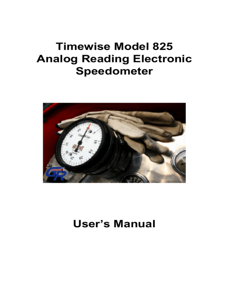
Timewise Model 825 Analog Reading Electronic Speedometer User’s Manual Specifications The Timewise Model 825 analog reading electronic speedometer eliminates the traditional problems associated with mechanical speedometers used in perfect time rallies such as the Great Race. The Model 825 speedometer has no variation with temperature, no accuracy degradation over time, and no repeatability issues. Dimensions: • Bezel diameter: 4.187" • Bezel thickness: 0.75" • Barrel diameter: 4.00" • Total depth: 3.50" (including bezel thickness, but not including rear surface screw heads or grounding lug). The rear surface screw heads add 0.1", and the grounding lug extends about 0.75" • Once plugged in, the magnet sensor cable requires a minimum bend radius of about 1.00" • The power cord requires a minimum bend radius of about 0.375" Accuracy: (Variation from the speedometer reading compared to actual speed) • +/– .0125 mph Repeatability: (Variation between readings at the same speed, made at different times) • +/– .0125 mph Resolution: (Speed variation needed to cause the needle to move) • +/– .0125 mph Variation with temperature: • 0 mph Aging (Lifetime Degradation): • 0 mph Factor adjustment sensitivity (factor resolution): • +/– 1 sec/hr Minimum reading with accuracy • 5 mph Maximum speed with accuracy • 100 mph Page 2 Calibration Information Each Model 825 speedometer is supplied with its own calibration certificate. The certificate is a chart listing the displayed speed offset due to the variations between each printed dial faceplate, as well as the mechanical tolerances within the speedometer. The errors due to these physical differences are generally so small that many rallyists simply disregard the information presented in the chart. Should you wish to keep the calibration certificate with the speedometer, its adhesive backing allows you to attach it to the cylindrical body of the speedometer. The inherent linearity of the speedometer mechanism eliminates the need to remark the dial for any installation. Note: The Model 825 speedometer has faceplate dial indicator marks every 1 mph, with 5 mph numbered increments. The 0 mph speed mark is the same as the 50 mph mark. That is, at zero speed the needle will point to the 50 mph mark. The speedometer needle in the Model 825 Speedometer may not precisely point to the middle of the “zero” indicator mark (50) when the speedometer is not powered or the vehicle is not moving. This offset at zero speed is due to a power savings mode of the speedometer’s firmware. When vehicle speed is zero, the microprocessor removes all power from the stepper motor drive circuitry, letting the stepper motor rest in its most energy efficient position. This sometimes results in an extremely small visible offset from the center of the zero speed mark. The speedometer is still perfectly calibrated at all speeds. Miles per Hour or Kilometers per Hour? The Timewise Model 825 speedometer indicator dial is marked in “units per hour” increments. The units can be miles or kilometers. The factor (explained later in “Setting the Factor Switches”) is what distinguishes whether the speedometer indicates miles per hour or kilometers per hour. Throughout this manual the terms “miles per hour” and “mph” can be changed to “kilometers per hour” and “kph” as needed. Once you have determined a proper factor for showing miles per hour, simply multiply that factor by 1.609344 for a new factor to be used to measure in kilometers per hour. Page 3 Speed Range The Model 825 speedometer dial has 1 mph tick marks, with 5 mph numbered increments. The 0 mph mark is the same as the 50 mph mark. That is, at zero speed the needle will point to the 50 mark. Although the speedometer appears to read only up to 50 mph full scale, it is usable to 150 mph. For speeds greater than 50 mph, simply add 50 (or 100) to the indicated faceplate value when the needle is on its second (or third) time around. For example, a speed of 70 mph is indicated as 20 after the needle rotates past the 50 mark. There is no loss of accuracy as the needle circles the dial multiple times. The 1 mile per hour increments are approximately 1/4 inch apart, allowing easy interpolation when fractional speeds are targeted. The speedometer will function down to 4.5 mph. Speeds lower than 4.5 mph will be displayed as 0 mph. The 4.5 mph minimum limit is a calculated speed using the highest anticipated factor of 5900. (See information later regarding setting the factor switches.) For installations that use a factor lower than 5900, the speedometer may read lower than 4.5 mph before dropping to zero. When running at speeds between zero and 4.5 mph, the needle may bounce between zero (50) and five. This is not indicative of a problem. It is simply the result of a microprocessor inside the speedometer alternately evaluating vehicle speed as zero and then some other speed close to 4 mph. Electrical Power The Timewise 825 speedometer operates from nominal 12 Volt DC negative ground vehicle power. A voltage from 9 to 14 Volts DC is tolerated. The speedometer cannot be powered by a 6 Volt DC power supply. If you have a 6 Volt vehicle, the speedometer must be powered off a separate 12 Volt battery. A motorcycle or garden tractor battery is fine. When using a separate 12 Volt battery, you may want to connect the negative side of the battery to the chassis of the vehicle (even if the vehicle has a positive ground). Current consumption for the speedometer is about 330 milliamps while the car is moving, and about 40 milliamps while stopped. When using a separate battery to power the speedometer, that battery must have a minimum capacity of 5 AHrs (amp-hours) to ensure that the speedometer operates throughout a day without a recharge. Page 4 Positive and Negative Power Connections The power connections for the speedometer must be made with care. The black wire must connect to the negative (–) potential of the battery and the red wire must connect to the positive (+12V) potential of the battery. Attaching both leads securely is mandatory. A momentary loss of electrical contact by either wire while the car is moving will cause a malfunction. Specifically, an intermittent power connection while the car is moving will cause the zero speed point on the speedometer to be lost. Should this happen, the needle will not return to zero when you stop and all other speeds will be in error by a fixed amount. The only way the speedometer can lose its zero point is when a power interruption occurs while the needle is not pointing at “0”. There is a procedure described later in this manual detailing how to fix a “lost zero”, but you are much better off preventing such a problem in the first place. The +12V wire must make continuous contact to a circuit that will never lose power while driving, rolling, or starting the vehicle. A good attachment point for the red wire is at the fuse box. Here, the positive potential cable from the battery brings uninterrupted power to all circuits in the vehicle. The red wire is supplied with a slip-in connector that may fit between a fuse and its holder. Several other attachment methods include: attaching to the power distribution panel screw terminals provided in some vehicles, removing the fuse box and attaching to a terminal on its underside, soldering (or crimping) directly to the 12 volt cable connector at the battery terminal, or tapping a circuit that always powers an electrical accessory. If you attach the positive (red) wire to a circuit already protected by a fuse, keep in mind that a problem elsewhere in the vehicle may blow that fuse and disable the speedometer. Make certain that the vehicle fuse is free of corrosion and makes continuous contact with its holder. Connection of the negative (black) wire can be to a screw or bolt on the chassis that is near the point of attachment for the red wire. The connection must be free of dirt, oil, grease, and paint. Be careful not over tighten the connection, as you may weaken the wire by breaking some of its individual fine wire strands. Important! If the supplied power cord consists of two individual wires (black and red), twist the wires around each other approximately one turn for every inch of travel. (It is not necessary to twist the two wires in the black “zip cord” style extension cable.) The red and black wires must be attached to points that are as close to each other as reasonably possible. Do not attach one wire to a Page 5 point on the chassis directly behind the speedometer and run the other lead a long distance to the fuse box or battery. By doing so, you would create a loop antenna that can pick up all manner of radiated energy. Such energy cannot be filtered out of the power line without prohibitively expensive electronics. Also important! When routing the power wires, make certain that the in-line fuse holder has some freedom of movement. If the wire either side of the fuse holder is pulled, a contact inside the fuse holder can be stressed. The fuse within the fuse holder may then lose contact to the wire. This may occur only when the vehicle is jarred by a bump in the road. Grounding the Speedometer Case In addition to the standard positive and negative electrical connections, the speedometer case should be grounded to the chassis of the vehicle. Traditionally, a good case ground connection shields sensitive electrical components from radiated electrical noise. Unfortunately, on old cars the chassis and engine grounding interconnection are often very poor. When the speedometer case is attached to a poorly grounded chassis, the connection simply acts as a path for noise to enter the speedometer. As a result, there are two recommendations for grounding the speedometer case. Recommendation 1 Don't ground the case. On old cars with poor grounding between the engine, chassis and battery, isolating the speedometer case seems to be the preferred configuration. The speedometer case needs to be completely isolated from the car ground. This includes your mounting bracket/mechanism. Wrap insulating tape around the bracket connections or use some other non-conductive material to keep the case isolated. Recommendation 2 Grounding the case is beneficial if the car has a good solid ground. When the speedometer case is connected to a properly grounded chassis, electrical noise and static discharges are dissipated along a path that doesn't interfere with the power supplied to the instrument. Grounding the speedometer is accomplished in a similar manner to grounding a radio. Page 6 On early style bare aluminum body speedometers, a very good ground can be made by clamping the body of the speedometer to the chassis using two large metal hose clamps. The black anodized body of the later style speedometer is an insulator so a hose clamp will not make a ground connection. To ground these speedometers, you’ll need to attach a heavy gauge ground wire to the threaded grounding stud on the back of the unit. Simply run a length of heavy gauge wire from the grounding stud to a nearby screw or bolt on the chassis. The thicker the wire, the better. Also, the shorter the wire, the better. See the discussion later on Electrical Noise Problems for more information. The Transducer (Pulse Sensor or Pick-up) The Model 825 speedometer uses a special "transducer" to convert vehicle motion into electrical pulses. As the vehicle moves, the electronics inside the speedometer measure the time between pulses generated by the transducer. Using this time measurement and information about the distance traveled between pulses, a computer inside the speedometer calculates your speed. The transducer must be mounted to your car. There are two styles of transducers that can be used. The most common style of transducer is a two-piece arrangement. This style of transducer consists of a sensor and separate magnets. Both of these items are supplied when the Model 825 speedometer is ordered as a Great Race package. The magnets are attached to the driveshaft or a wheel. A mounting bracket you must design and fabricate is used to hold the sensor. The bracket is attached to the vehicle so that the magnets pass the end of the sensor as the vehicle moves. When the North or South pole of the magnets pass 3/8 to 5/8 inch from the end of the sensor, an electrical signal is generated and the speedometer computes your speed. (Actually, the magnets can pass closer to the sensor, but you risk the magnets hitting the sensor if the bracket wiggles or the wheel or driveshaft wobbles. The non-pole sides of the magnet will not generate a signal.) A second style of transducer is a "one-piece" or "speedometer cable" transducer. (The speedometer cable transducer is optional.) The speedometer cable transducer attaches between the end of the speedometer cable and the vehicle’s original speedometer, or to the transmission or overdrive in place of the speedometer cable itself. The self-contained mechanism produces electrical pulses as the speedometer cable spins. Two pulses are generated for each Page 7 revolution of the speedometer cable. Speedometer cable transducers can be installed on most vehicles providing the cable connection method is one available from Timewise. If you wish to use this option, contact Timewise. The cost for this type of transducer ranges from $85 to $100, depending on the requirements of your vehicle. Installing the Transducer and Magnets (The following paragraphs describe installation of the two-piece transducer system supplied with the speedometer. If you are using a speedometer cable transducer, installation simply consists of connecting the transducer to the transmission or to the end of the speedometer cable.) The magnets of a two-piece transducer system may be installed on the driveshaft or on a wheel. The transducer is mounted such that it “sees” the magnets as they spin past the tip of the transducer. Regardless of the chosen mounting location, rule number one is to make sure the overall installation is rugged and secure. If the rotation of a wheel is used as the source of vehicle movement, two magnets must be used. The magnets must pass 3/8 to 5/8 inch from the tip of the sensor. You must use two, and only two, magnets. If more than two magnets were to be used, any unequal rotational distance between the magnets will cause a wavering speedometer needle. Extra magnets are provided, but only two are required. If driveshaft rotation is used as the source of vehicle movement, you must only use one magnet. Important! Be careful when handling magnets near ferrous metals or other magnets. If a magnet slips from your fingers, it may shatter on impact. Even if it doesn’t break, the physical shock will weaken its magnetic field. When mounting magnets, do not recess them into a hole drilled into a metal surface, or locate them within a depression in the metal. Doing so will change the shape of the magnetic field which naturally surrounds a magnet, drawing it closer to the surrounding surface. When the magnetic field does not extend far from the magnet, the transducer may not produce the required electrical pulses. Also, do not machine a magnet to fit a particular location! Cutting, drilling, or grinding a magnet will reduce its magnetic field strength by both material loss Page 8 and stress-induced demagnetization. The magnetic field of the remaining material may not be sufficient to stimulate the sensor. If you need magnets of a different shape, size, or magnetic orientation, please contact Timewise. Any magnet with a single pair of North and South poles will work fine. We do not generally recommend that you attach magnets to the brake drum. The high heat generated during hard braking can bring the magnet to its "Curie temperature". When a magnet reaches its Curie temperature, it will completely lose its magnetism. Such extreme heat can also weaken its attachment method. If you do mount the magnets to the brake drum, make a small bracket to raise the magnets off the drum. We have seen successful installations which used a bracket formed somewhat in the shape of the Greek letter omega ( Ω ). The circular center of the bracket was sized to fit the “button” magnets provided with the speedometer. Each "foot" of the bracket had a small hole which allowed it to be attached to the brake drum (with holes drilled and tapped into its outer perimeter). This installation held the magnets off the hot brake drum. When magnets are installed on the driveshaft, you may see occasional needle bounce (once every 10 minutes or so) caused by backlash in the drive train. We have noticed that upon a sudden speed change, the driveshaft of an old car may actually pause or even spin backwards for a moment. If the magnet is exciting the sensor when this occurs, an extra pulse can be seen. As mentioned, use only one magnet when sensing the rotation of a driveshaft. When sensing rotation of a wheel, it’s not always obvious which wheel to use. Front wheels are generally non-driven and experience less wheel slippage. However, the front suspension experiences more weight reduction due to aerodynamic lift. With front-end lift, the rolling circumference of the front tires grows. On light automobiles with large exposed flare fenders, the change in lift between 20 mph and 50 mph can produce up to a 5% error in the perfect driving time. Therefore, on light vehicles a rear wheel installation is often a better choice. Regardless of whether you use a front or rear wheel, use the wheel closer to the center of the road. When attaching the magnets, use a good, strong epoxy. The best readily available epoxy we've found is "JB Weld". Most hardware stores carry this two-part epoxy. JB Weld has a coefficient of expansion close to that of the Page 9 magnets and metals on the car. Super-glues and brittle adhesives will not accommodate expansion of the metals. RTV silicone adhesives remain flexible when cured, so they may also work well. Locate two magnets 180 degrees apart on the rotating member. Exact spacing between the magnets is not critical. The speedometer averages the time that elapses between sequences of three pulses. Note that whether one or two magnets are used, any sequence of three pulses starts and stops at the same magnet. Were you to use more than two magnets, the angular spacing between each magnet would have to be precisely the same, otherwise the "3 pulse sequence" time would change depending on which magnet started the measurement. (This is why we stipulate that you should not use more than two magnets.) Thoroughly clean the intended location for each magnet to remove all dirt, rust, grease, oil, and paint. You can use navel jelly or a little vinegar to remove small amounts of surface rust. Use emery paper or a wire brush to remove paint and heavy deposits of rust. Following this, clean the surface with alcohol to remove all residues. Clean the magnet as well, removing anything that has accumulated during handling. Prepare the epoxy according to the directions on the package. Now carefully coat the surface of the magnet that will lie against the mounting surface. Use just enough to fill small gaps. Too much epoxy and the magnet may not lie flat. Place the magnet in position and use additional epoxy to fill-in along the sides of the magnet. Apply a liberal amount here, but do not cover the upper surface of the magnet. And don’t form a ridge around the magnet that will interfere with the sensor. Some people use JB Weld only to attach the magnet and, once the epoxy has cured, fill in the sides of the magnet with silicon adhesive. When mounting the magnet to a driveshaft or rotating flange, you may wish to wrap nylon-reinforced tape around the rotating member to hold the magnet in place while the epoxy is curing. Keeping this tape in place after the epoxy cures provides additional holding power should the epoxy bond fail. Always wrap the tape in the direction opposite the normal turning motion of rotating member. Caution! Improperly applied adhesive tape may begin to unravel and get caught between the sensor and rotating member, possibly damaging the transducer and/or magnet. When mounting magnets on a wheel, locate them so there is some support in the direction of the centrifugal force they will experience. Caution! An Page 10 improperly epoxied magnet could come off while spin balancing the wheel. Also, if you are attaching magnets to a wheel that is removed from the vehicle, replace the wheel only after the epoxy has cured. This will prevent accidental movement of the magnets. After the magnets have been installed, locate the sensor as necessary using your custom designed bracket and mounting method. Position the sensor to achieve the required 3/8 to 5/8 inch gap as the magnets pass by. The body of the sensor is threaded along its entire length to aid in the adjustment. Route the transducer cable such that it will not be snagged by the suspension’s movement or by road debris. Avoid routing the cable near electrical noise generators such as the distributor coil, spark plug wires, horn, electrical wiper motors, etc. Once everything is in place, the magnet sensing transducer will provide years of reliable service. The sensor is not affected by water, dust, or extreme temperature Note: If a magnet does get dislodged while using the speedometer, the displayed speed will be exactly 1/2 your actual speed. Drive at precisely half the given speed and your score will not be affected. Setting the Factor Switches Prior to setting the factor switches, inflate the vehicle tires to your desired optimal value. On the back of the speedometer, there are four holes that allow access to the factor switches. When setting the factor switches, turn the speedometer around so you can look at it from the back. Then rotate the speedometer on its central axis so the transducer input connector is to your right (the 3 o’clock position) and the four factor switch access holes are parallel to the ground. The factor value is read from left to right when viewing the speedometer from the back. Adjustments to the rotary switch positions are performed using a small flat-blade screwdriver. Turn the small arrow on each switch to point to the desired value, 0 through 9. If you reverse the order of the digits, you'll never be able to determine a correct factor...this is the most common cause for confusion when setting a factor. Page 11 The factor value is the distance, in inches, the vehicle travels to produce ten pulses from the transducer. The factor has a resolution of xxx.x inches (i.e., tenths of inches). As an example, if ten pulses are produced every 331.4 inches, the factor is set to 3314. The switches do not show the decimal point. (If you measure in centimeters, divide the distance by 2.54 to determine the factor.) If you want to display kilometers per hour (instead of miles per hour) and you measured the distance in inches, multiply your measurement by 1.609344; or, if you measured in centimeters, multiply your measurement by 0.6336. When using two magnets on a wheel, ten pulses are produced for every five wheel revolutions. Here's a simple way to determine the distance traveled for ten pulses. First, make a caulk line on the tire and roll the vehicle forward until the caulk mark touches the road, and put a caulk mark on the road at that point. Now roll the car forward five revolutions of the tire. When the tire’s caulk mark touches the road on the fifth revolution, make another mark at that point on the road. Then measure the distance between the two caulk marks on the road. Measure to a resolution of a tenth of an inch. This distance is the factor. Alternatively, measure the distance traveled in just one wheel revolution. In this case, only two pulses would have occurred, not ten. The factor will be five Page 12 times the distance you measure. We suggest you use five wheel revolutions simply to be more precise. Install only one magnet on the driveshaft when it is used as the indicator of vehicle movement. The factor will then be the distance the car travels in ten revolutions of the driveshaft. Be as precise as you can...that's why we suggest ten revolutions of the driveshaft. If you measure the distance the car travels during one revolution of the driveshaft, the factor is ten times that distance. Obviously, it is rather difficult to measure the distance while watching the driveshaft. For now, measure as accurately as you can. You'll have many opportunities later to adjust the factor. When using a Timewise supplied speedometer cable transducer, the factor is the distance the vehicle travels every five cable revolutions. This is because there are two pulses produced per cable revolution. If you know the exact number of speedometer cable revolutions per mile for your vehicle, you can simply calculate the factor. For example, if the speedometer cable rotates 1200 times per mile, there would be 2400 pulses produced by the speedometer cable transducer each mile. Since there are 63360 inches in one mile, 10 pulses occur every 264.0 inches (63360/2400 * 10). A factor of 2640 would be used. Another way to determine a factor involves timing your travel through a known distance. That is, drive a measured distance at a set speed and note your error in the ideal travel time through the course. The error in your driving time is due to the error in your factor. From this information, you can correct the factor. For example, set the factor to any value. Let’s use 3000. Then drive a 1/10th mile course at exactly 30 mph. Precisely measure the time it takes to complete the run, from start to finish. If the factor of 3000 had been perfect, and therefore the speedometer would have been reading perfectly, the 1/10th mile run would have taken exactly 12 seconds (0.20 minutes). Any error from this perfect time is due to the error in the factor. To determine a corrected factor, divide 12 seconds by the measured time. Then multiply that result by the factor (3000). The final number is the corrected factor for your installation. Note that when setting up a rally course, the rallymaster does not always use perfect statute miles. This is because rallymasters expects you to adapt to their distance measurement standard, even if it's not the same as the national standard. This is the typical scenario in every rally...the rallymaster sets the standard, not the public governing body. As a result, you will have to adjust your factor at every rally. And on the Great Race, you'll probably have to Page 13 adjust your factor every day. As such, the setting of your factor, and therefore the speed you see on the speedometer, must be corrected as needed. To change your speedometer so it exactly matches the rallymaster’s, simply correct your factor. The correction is a percentage change. The percentage change is the percentage error between your time to run a speedometer calibration run and the ideal time stipulated by the rallymaster. That is: Change in Factor = Percentage error in calibration run * Old Factor. To help you determine whether you increase or decrease the factor, use this rule: “Too slow on the course, reduce the factor”; “Too fast on the course, increase the factor”. We also say, “Smaller factors make you arrive Sooner”; and, “Larger factors make you arrive Later”. Or, “SS” and “LL”. For example: If you are 9 seconds late in a one hour speedometer run, your error is 9/3600 (remember, one hour is 3600 seconds). This is a 0.25% error (9/3600 x 100 = 0.25%). This percentage, multiplied by your original factor, gives the adjustment. You had arrived late…you want to arrive sooner. Make the factor smaller by 0.25% because you need to arrive sooner. After the adjustment, your speedometer will exactly match the rallymaster's. Another example: If a speedometer calibration run is supposed to take exactly 15 minutes, and you arrive 1 second too soon, the error is 4 seconds/hour…or 4/3600, or 0.11%. Make the factor 0.11% larger to arrive later. Here's another way you can correct for small differences between the speedometer's indicated speed and the rallymaster's "official" speed. Since a change in tire pressure alters the rolling circumference of a tire, a tire pressure adjustment can be used to correct your actual speed. Our experience indicates that a 1 psi change in tire pressure typically results in a 1 to 2 second/hour driving time change (regardless of the distance). In fact, tire pressure changes can be used to adjust for differences between your speedometer and the rallymaster's. A 10 psi pressure adjustment can make a 10 to 20 sec/hour correction. This is generally enough to align your speedometer to the rallymaster's. There would be no need to change the factor. Changing tire pressure can also accommodate long-term tire wear. Note to rallyists who have a Timewise rally computer: The factor in the Model 825 speedometer uses “inches” as a unit of measure, whereas Timewise Page 14 rally computers use factor units of "miles". There are 63360 inches in a mile. To convert a Model 825 speedometer factor to a Timewise rally computer factor, divide the speedometer factor by 0.06336. (This conversion figure shifts the decimal point as needed.) Speedometer Factor / 0.06336 = Rally Computer Factor or multiply by 15.7828 (the reciprocal of 0.06336) Speedometer Factor * 15.7828 = Rally Computer Factor If you are converting a Timewise rally computer’s factor to one appropriate for the Model 825 speedometer, do the inverse. Rally Computer Factor * 0.06336 = Speedometer Factor or divide by 15.7828 Rally Computer Factor / 15.7828 = Speedometer Factor Compensating for Minor Speedometer Inaccuracies Each Timewise Model 825 speedometer is supplied with a calibration chart printed on an adhesive backed label. Some rallyists attach this chart to the cylindrical body of the speedometer. The calibration chart can be used to correct your driving time to account for subtle faceplate dial printing variations, and for the tolerances of the stepper motor mechanics. The calibration chart lists the time error that will accumulate after driving one hour at each 5 mph speed increment from 10 to 50 mph. That is, while driving for an entire hour at a listed speed, you will accumulate the indicated timing error. This is known as the “seconds per hour” error. The average error for all speeds is generally less than +/- 0.5 second/hour. That being the case, many rallyists simply disregard the chart information. However, if your speedometer has specific speeds with errors of one or more seconds/hour, you should consider correcting your travel time after driving at any of those speeds for extended periods. For example, if the error at 15 mph is 3 sec/hr, and you drive at 15 mph for one hour, correct your travel time by 3 Page 15 seconds after that one hour. Or you can adjust 1 second every 20 minutes; or 0.5 second every 10 minutes, etc. Should you wish to have your speedometer recalibrated, contact Timewise. There is a fee of $60 for this service. Re-Zeroing the Needle You must be absolutely certain that power connections to the speedometer are proper and uninterrupted whenever your vehicle is moving. Here's why: Every time power is applied to the speedometer, a microprocessor inside assumes the starting needle position is at 0 mph (at the “50” mark). As your speed changes, the microprocessor directs a stepper motor to move the needle a calculated deflection from a known previous position. If power to the speedometer is interrupted when you are not at zero mph, the needle cannot return to its “0” starting point. Subsequently, when power is re-applied, the initial starting position for the needle will be wrong. Therefore, never allow power to the speedometer to be interrupted while the needle is indicating a vehicle speed other than 0 mph! Should power be interrupted when the speedometer was not indicating zero speed, you must manually re-zero the speedometer. The procedure is simple. To manually reposition the needle to the true zero point, you'll need to remove the protective glass cover on the front of the speedometer. On first generation Model 825 speedometers (silver body), a chrome-plated locking ring holds the glass cover in place. Use a small flat blade screwdriver to carefully flex the locking ring inward so that it can be removed. With the ring removed, you can lift the glass off. A small suction cup helps. Second generation Model 825 speedometers (black body) have the cover glass held in place with a screw-on bezel. Simply unscrew the bezel and lift the glass to gain access to the needle. A small suction cup helps. The glass may lift off with the bezel. You must be stopped when rotating the needle, but you can rotate the needle with or without power applied to the speedometer. We suggest you rotate the needle only clockwise to avoid loosening the needle’s attachment screw. Grasp the needle close to its center of rotation and slowly rotate the needle around to Page 16 zero. If you do this while power is applied to the speedometer, you will feel considerable resistance while rotating the needle. This is because you must overcome strong magnetic fields generated by the energized stepper motor. Even when power is not applied to the speedometer you will feel the tug of the permanent magnets inside the motor. When you are satisfied that the needle is aligned to zero, replace the cover glass and then the locking ring or bezel. NOTE! On a few very early Model 825 speedometers, there was a small adjustment screw along the needle pointer near its pivot point. This adjustment screw was used to calibrate the speedometer. Do not turn this screw. Also, note that the speedometer faceplate (the printed dial) is held in place with two screws. These screws allow the faceplate to be precisely oriented during the calibration process. Never loosen these screws! If you do, the speedometer will need to be recalibrated. There is a fee of $60 for this service. Electrical Noise Problems Electrical noise is a problem for electronic devices in any car. This is particularly true in old cars. A symptom of electrical noise is a speedometer needle that does not hold steady while you drive at a constant speed. In fact, under severe electrical noise, the needle may spin wildly around the dial. Noise suppression hardware and software are designed into the speedometer. These features eliminate many problems caused by random low levels of noise. However, the noise generated by solid ignition wires is so great that it cannot be rejected completely. If you have solid ignition wires installed in your vehicle, you will be plagued with electrical noise trouble. You absolutely must change old "non-resistive" ignition wires or copper straps to modern "resistive" wires. You may also need to use resistive spark plugs. If you are using resistive ignition wires and continue to have noise problems, improve the ground connections between the chassis, engine, and battery. A good electrical path between these vehicle components is critical. We cannot over-emphasize the importance of heavy gauge ground straps and strong, clean ground connections. Everything in your car will run better. Installing an electrical noise filter in-line with the power leads can reduce electrical interference on the power leads. Car audio installers may be able to supply such an electrical noise filter. Page 17 Problem Solving The following is a list of reported problems and suggested solutions. 1. Speed readings bounce higher than the actual speed. • In speedometer cable transducer installations, or two-piece transducer installations with magnets attached to a wheel or driveshaft, random high speed readings can occur when electrical noise is excessive. In two-piece transducer installations with a magnet attached to a driveshaft, random high speed readings can be caused by driveshaft backlash. Make certain that you are using only one magnet on the driveshaft. If the problem persists, you may have to change the installation to sense the rotation of a wheel. 2. Speed readings bounce both ways: • This can occur in speedometer cable transducer installations if the threaded connection is loose or not perfectly straight. Recheck the threaded connections. If the problem continues, the erratic reading may be occurring because the gears in the transmission are exhibiting backlash. In this situation, you may have to utilize the two-piece magnetic transducer. 3. Speedometer no longer returns to zero when stopped. • This is due to a power interruption. Review the electrical power section of this manual and check both power connections. You’ll need to manually re-zero the speedometer needle. 4. Speed readings bounce lower than actual values and then recover. • The sensor missed a pulse. A weak or improperly oriented magnet, or a misaligned sensor, can cause missed pulses. There could also be excessive tension on the transducer connector at the back of the speedometer…the connection might temporarily open, causing missed pulses. 5. The indicated speed suddenly drops to half its correct value (applies to installations having two magnets on a wheel). • A magnet has fallen off the wheel, or the magnet is damaged 6. The indicated speed drops to zero and stays there. (The magnets can be on a wheel or driveshaft.) Page 18 • The magnet has fallen off the driveshaft, or both magnets have fallen off the wheel. Or the transducer connection to the speedometer is loose. Or the transducer cable is damaged. 7. Speed drops to zero or close to zero and stays there until you slow to nearly a stop. The speedometer then recovers and operates normally. The zero speed point is maintained. • This is an electrical noise or erratic pulse problem revealed by a design feature of the speedometer. If your speed is greater than 40 mph when pulses become erratic, the microprocessor interprets the change in pulse rate as electrical noise. The microprocessor then places the needle at zero until your speed can be properly calculated. When you slow down or stop, the microprocessor will synchronize to the lower speed and allow the speedometer to function normally again. To solve this problem, eliminate the electrical noise or find out why there are missing or erratic pulses. The problem also shows up when two magnets are used on a driveshaft. Remove one of the magnets and double the factor. 8. The speedometer needle is not precisely in the middle of the “zero” mark when the vehicle is not moving. • This is due to a power savings mode of the speedometer’s firmware. When vehicle speed is determined to be zero, the microprocessor removes all power from the stepper motor drive circuitry, and lets the stepper motor rest in an energy efficient position. This sometimes results in an extremely small visible offset from the center of the zero mark – up to half the width of the mark. The speedometer is still perfectly calibrated. 9. After calculating a new factor, that value does not make the speedometer measure properly. • This is likely due to setting the four factor switches in reverse order. When setting the factor switches, turn the speedometer around to look at it from the back. Then rotate it so the transducer input connector is to your right (the 3 o’clock position) and the four factor switch access holes are parallel to the ground. When viewing the speedometer from the rear, the factor is set from left to right. To repeat: Turn the speedometer around to look at it from the rear. Then rotate it so the transducer connector is to your right (the 3 o’clock position when viewing the speedometer from the back) so the four rear panel access holes are oriented parallel to the ground. Page 19
