1 Introduction 2 Derivation of Faraday Rotation
advertisement
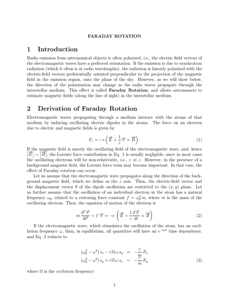
FARADAY ROTATION 1 Introduction Radio emission from astronomical objects is often polarized, i.e., the electric field vectors of the electromagnetic waves have a preferred orientation. If the emission is due to synchrotron radiation (which it often is at radio wavelengths), the radiation is linearly polarized with the electric-field vectors preferentially oriented perpendicular to the projection of the magnetic field in the emission region, onto the plane of the sky. However, as we will show below, the direction of the polarization may change as the radio waves propagate through the interstellar medium. This effect is called Faraday Rotation, and allows astronomers to estimate magnetic fields (along the line of sight) in the interstellar medium. 2 Derivation of Faraday Rotation Electromagnetic waves propagating through a medium interact with the atoms of that medium by inducing oscillating electric dipoles in the atoms. The force on an electron due to electric and magnetic fields is given by 1− − → − → v ×B . (1) Fe = −e E + → c If the field is merely the oscillating field of the electromagnetic wave, and, hence − magnetic − → → E ∼ B , the Lorentz force contribution in Eq. 1 is usually negligible, since in most cases the oscillating electrons will be non-relativistic, i.e., v ≪ c. However, in the presence of a background magnetic field, the Lorentz force term may become important. In that case, the effect of Faraday rotation can occur. Let us assume that the electromagnetic wave propagates along the direction of the background magnetic field, which we define as the z axis. Then, the electric-field vector and the displacement vector s of the dipole oscillation are restricted to the (x, y) plane. Let us further assume that the oscillation of an individual electron in the atom has a natural frequency ω0 , related to a restoring force constant f = ω02 m, where m is the mass of the oscillating electron. Then, the equation of motion of the electron is → d2 − s → m 2 +f− s = −e dt ! → 1 d− s − → → − E+ ×B c dt (2) If the electromagnetic wave, which stimulates the oscillation of the atom, has an oscillation frequency ω, then, in equilibrium, all quantities will have an e−iωt time dependence, and Eq. 2 reduces to e Ex m e = − Ey m (ω02 − ω 2 ) sx − i Ω ω sy = − (ω02 − ω 2 ) sy + i Ω ω sx where Ω is the cyclotron frequency: 1 (3) eB (4) mc Let us now introduce electric-field and displacement vectors corresponding to circularly polarized waves: Ω= E± ≡ Ex ± i Ey and s± ≡ sx ± i sy (5) We note that the original, linearly polarized waves can be re-covered as Ex = (1/2) (E+ +E− ) and Ey = (1/2i) (E+ − E− ). Inserting Eqs. 5 into Eqs. 2 and adding and subtracting, respectively, the two equations from each other, we find e E+ m e = − E− m (ω02 − ω 2 − ω Ω) s+ = − (ω02 − ω 2 + ω Ω) s− (6) Now, from the induced dipole moments P± , P± = ne e2 E± m (ω02 − ω 2 ∓ ω Ω) (7) where ne is the number density of electrons, we can find the polarizability χ± ≡ 4πP± /E± and, hence, the index of refraction for left-handed and right-handed circularly polarized waves as n± = v u u t1 + 4π ne e2 m (ω02 − ω 2 ∓ ω Ω) (8) Obviously, n+ > n− , so that the left-handed circularly polarized wave will travel at a slightly lower phase velocity vp = ωc/n than the right-handed wave. The z- and timedependent electric-field vector of a left-handed circularly polarized wave is given by ω [n+ z − ct] = E0 cos c ω L Ey (z, t) = E0 sin [n+ z − ct] c ExL (z, t) (9) and, correspondingly, for the right-handed circularly polarized wave: ω = E0 cos [n− z − ct] c ω R Ey (z, t) = −E0 sin [n− z − ct] c ExR (z, t) (10) A linearly polarized wave is the superposition of a left-handed and a right-handed circularly polarized wave. Thus, adding Eqs. 9 and 10 to find the solution for the propagation of a linearly polarized wave through a magnetized medium, we have 2 Ex Ey ω ω = 2 E0 cos [nz − ct] cos [n+ − n− ] z 2c c ω ω [nz − ct] sin [n+ − n− ] z = 2 E0 cos c 2c (11) where 1 (n+ + n− ) (12) 2 is the average refractive index. The polarization angle with χ with respect to the x axis is n≡ ω Ey = (n+ − n− ) z (13) Ex 2c which obviously changes linearly with propagation distance z. The frequencies of electromagnetic radiation and the natural oscillation of atomic dipoles are typically much larger than the cyclotron frequency, ω, ω0 ≫ Ω. In that limit, we find χ = arctan n≈ 1+ and 4π ne e2 m (ω02 − ω 2 ) 4π ne e2 ω Ω n+ − n− ≈ m (ω02 − ω 2)2 (14) (15) so that the change of the polarization angle with propagation distance is given by 2π ne e2 ω 2 Ω dχ = dz m c (ω02 − ω 2 )2 (16) Furthermore, electromagnetic radiation typically has frequencies much higher than the natural oscillation frequencies of atoms, ω ≫ ω0 . With this, and using Eq. 4, and replacing ω = 2π c/λ, where λ is the wavelength, we find for the change in polarization angle: e3 λ2 ∆χ = 2π (mc2 )2 Z ne (z) Bk (z) dz (17) LOS where the integral extends over the line of sight between the source and the observer, and Bk is the component of the magnetic field along the line of sight. Eq. 17 is often written in terms of the Rotation Measure (RM), as ∆χ = RM λ2 where RM = 2.64 × 10 −17 −1 Gauss Z LOS −2 which will carry a unit of cm . 3 (18) ne (z) Bk (z) dz (19) 3 Application The Faraday rotation effect (Eq. 18) allows us to measure an average of the magnetic field parallel to the line of sight, weighted by the electron density. Since one usually does not know the intrinsic polarization angle at the source, one needs polarization angle measurements χ1,2 at least at two different frequencies, λ1,2 , from which the rotation measure can be found as RM = χ2 − χ1 λ22 − λ21 (20) However, any polarization angle measurement has an ambiguity of any integer number of π, i.e., one can not distinguish between a polarization angle of χ or χ ± n π. In order to resolve this ambiguity, one typically uses three or more reference frequencies to determine the slope of χ vs. λ2 to find the RM. Given a prior knowledge of the electron density (and its spatial distribution) along the line of sight, the RM provides an estimate of the parallel magnetic field in the regions with high electron densities. One can see that, for a typical magnetic field of ∼ a few µG, densities of ne ∼ 1 cm−3 , along a typical sight line of ∼ a few kpc through / out of the Galaxy, one finds rotation measures of RM ∼ 1 cm−2 . Thus, the polarization angle of radio waves with wavelengths of 1 cm (ν = 30 GHz), will rotate by an angle of ∼ 1 rad, or ∼ 57o . 4
