Q U I C K S TA R T G U I D E
|
K304 • K304E • K308
4/8 Ports High Security
KM Switch
Models:
K304 – 4 Ports High Security KM Switch
K304E – 4 Ports High Security KM Switch with DPP
K308 – 8 Ports High Security KM Switch
Q U I C K
S T A R T
G U I D E
HSL Secure KM Switch enables users to simultaneously operate four or eight computers, each
with its own displays, using a single set of keyboard and mouse. The user can easily switch
between computers and displays by simply moving the cursor from one display to another.
For proper use, the HSL Secure KM Switch must be configured correctly according to the
actual placement of the displays, relative to each other.
This guide instructs how to install and configure the relative location of the displays to
match their physical locations.
There are two ways to configure the HSL Secure KM Switch with the actual display setup:
• Select one of the predefined setups
• Create and load a custom configuration file
Installation
Before configuring the HSL Secure KM Switch, connect all computers and components.
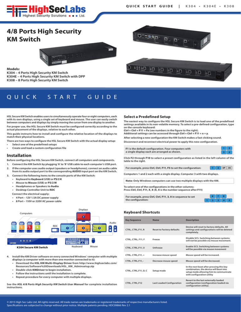
Select a Predefined Setup
The easiest way to configure the HSL Secure KM Switch is to load one of the predefined
settings available in its non-volatile memory. To select a pre-defined configuration, type
on the console keyboard:
Ctrl + Ctrl + F11 + Fx (see numbers in the figure to the right).
Additional settings can be accessed through Ctrl + Ctrl + F11 + x + y.
After selecting a new configuration the KM Switch makes a fast clicking sound.
Disconnect and reconnect electrical power to apply this new configuration.
F1 is the default configuration. Four computers with
a single display each are arranged as shown.
1
2
3
4
Click F2 through F10 to select a preset configuration as listed in the left column of the
table to the right.
1. Connect the KM Switch by plugging 'A' to 'B' USB cable to each computer’s USB port.
2. If the computer uses audio output (speakers or headphones), connect an audio cable
from its audio output port to the corresponding AUDIO input port on the KM Switch.
3. Connect the following items to the console ports of the KM Switch:
• Keyboard to Keyboard (USB) or PS/2 K
• Mouse to Mouse (USB) or PS/2 M
• Headphones or Speakers to Audio
• Desktop Controller Unit to RDC
For example, press Ctrl, Ctrl, F11, F5 to set the configuration:
1
2
3P
3S
Computers 1 and 2 each with a single display. Computer 3 with two displays.
Note: Only Windows computers can use two multiple displays with the KM.
To select one of the configurations in the other columns:
Press Ctrl, Ctrl, F11, X, X (X, X is the number sequence after F11)
Connect the electrical supply:
• 4 Port – 12V 1.5A DC power supply
• 8 Port – 110V or 220V AC power cable
For example, press Ctrl, Ctrl, F11, 3, 0 in sequence to set
the configuration:
Displays
1
6
7
8
2
3
4
5
Keyboard Shortcuts
Computers
3
Audio
1
2
1
3
2
3
4
RDC
1
2
4
4
K304 Secure KM Switch
Keyboard
Mouse
4. Install the KM Driver software on every connected Windows® computer with multiple
displays (a computer with more than one monitor connected to it):
• Download the HSL KM Multi-Display Driver from http://www.highseclabs.com/
Resources/Software%20Downloads/HSL_KM_Adminsetup.zip
• Double-click KMDriver to begin installation.
• Follow the instructions until the installation is complete.
• Repeat procedure for every computer with multiple displays.
See the HSL 4/8 Ports High Security KM Switch User Manual for complete installation
instructions.
Key Sequence
Name
Description
CTRL, CTRL,F11, R
Reset to Factory defaults
Device will reset to factory defaults. All
settings and configurations will be deleted
completely.
CTRL, CTRL, F11, F
Freeze
Disable SCS. Switching between systems
will not be possible via mouse movement.
CTRL, CTRL,F11, U
Unfreeze
Enable SCS. Switching between systems
will be possible via mouse movement
CTRL, CTRL,F11, +
Increase mouse speed
Mouse speed will be increased.
CTRL, CTRL,F11, -
Decrease mouse speed
Mouse speed will be decreased.
CTRL, CTRL,F11, D, C
Setup mode
In the next boot after pressing this key
combination, the device will boot into
setup mode allowing him to communicate
with configuration utility
CTRL, CTRL,F12
Last Loaded Configuration
Revert to the last externally loaded
configuration (configuration loaded via
configuration utility).
© 2015 High Sec Labs Ltd. All rights reserved. All trade names are trademarks or registered trademarks of respective manufacturers listed.
Specifications are subjected to change without prior notice. Multiple patents pending. HDC09866 Rev 2.1
Q U I C K S TA R T G U I D E
Advanced Setup
Creating and loading the custom configuration is a 2-step process:
• On a separate computer, create a custom configuration
• Load the configuration to the KM Switch
3.1
Connect a keyboard, mouse and display to a computer that will be connected to
the KM Switch.
3.2
On each computer, open the Screen Resolution dialog:
Control Panel > Display > Screen Resolution.
3.3
Note the display resolution in the Resolution field.
If the computer is connected to multiple displays,
set and note the resolution of the primary (main)
and secondary displays.
3.4
Move the secondary display relative to the
primary display, as they are physically located,
and note the coordinates.
Step 1 – Create a Custom Display Configuration
Note: To define a new configuration file, you will need to know the resolution and size of
every display, along with the coordinates of every secondary display (on a computer that
has more than one display connected to it). See Display Resolution and Coordinates for
instruction on how to get the resolution and coordinates of each display.
F1
F2
F3
F4
F5
F6
F7
F1
4
2
1S
1
3S
3
1P
3S
3P
3P
1S
1P
F2 1
F3
F4
F5 1
F6 1
1P
3
1S
4 F7 3 1P4 1S 1P3F11
1S4| 1 |37 F11
4 |1|7
F7 1P 1S F7
2
2
2P
2
4
3
2
1
F11 | 1 | 2 F11 | 1 | 2
1
3
3
1S 1P 1S
1
3S 3P F11
3S| 1 | 3 F11 | 1 | 3
2
2
3
1
2
1
2
1
2 1 (Factory
2
(Factory
(Factory
F1
F1 (Factory
F11
| 1 F11 |21 | 1
3
4
3
4 3 Default)
4 | 1 Default)
Default)
Default)
1P
3S
3P
1
3
2
1
3S
3
1
2
3P
F11 | 1 | 4 F11 | 1 | 4
3
F2 3 1 4 2 1 3 2 4 3
3P
42
1S
31
F2
3S
F3
1P
3S 1S
3P 1P
3P
1S
1P
F3
3S
3P
F4
1S
2
4
13
F11 | 1 | 9 F11 | 1 | 9
2
1P
F4
F9 3 1
1
2P
4 F62S 1 4 2P 12SF11
2P4| 12S
4 |1|6
| 6 F11
2
3
2
| 13P
| 5 F11
3P
1 3S
2 F53P 13S 2 13PF11
23S
3S | 1 | 5
F5
2S
1
F6
31
F9
1
1
3
1
3
2
2 | 1 | F11
F11
1 | 12| 1
3
2
F11 | 1 | F11
2 |1|2
1
3
1
2
3
2
2
3
1
1
3
1
2
1
1
3
2
F11 | 1 | F11
3 |1|3
2
1
2
3S
1
3P
2
1
3
2
3S
3P
1S
F11 | 2 | 1 F11 | 2 | 1
2
F111 | 2 | 2 F11 | 2 | 2
3
1P
1P
2
F11 | 2 | 3 F11 | 2 | 3
3
3S
3P
1
2
3
F11
2 | 2 | 4 F11 | 2 | 4
3
4
1
2 | 2 | 5 F11 | 2 | 5
F11
3
4
1
2
F11 | 2 | 6 F11 |12 | 62
24
2
3
1
3
1
F11 | 1 | F11
4 |1|4
2
3
1
3
1
4
2
F11 | 1 | F11
5 |1|5
3
1
3
3
3S
F111 | 2 | 7 F11 | 2 | 7
24
1
42
F11 | 1 | F11
6 |1|6
3
1
2
1
4
F11 | 1 | F11
7 |1|7
3
3
1 3F11
2 | 2 |38 F11 | 2 | 8
1
2
4
42
4
1
2
2
1
3S 3P
3
1
4
3P
2
2
31
3S
F11 | 1 | F11
8 |1|8
1
2
F11
| 2 | 9 F11 | 2 | 93
3P
F11 | 1 | F11
9 |1|9
2
1
2
1
3S
3P
3S
3P
2
1
2 3S
1 3P
3S 2
3P 1
F11 | 2 | F11
1 |2|1
3S
3P
F11 | 2 | F11
2 |2|2
75 | 386| F11
3 2 4F11
3 | 3 |43 F11 |53 | 36 F11
3 7| 35| 83 6
Only)
(8-Port
1 Only)
2 (8-Port
31
42
3 1Only)
4 2
1S 1P (8-Port
1S Only)(8-Port
3
2
1S
4
42
1P
3S
3P
2S
2P
F11 | 3 | 1 F11 | 3 | 1
1
2
1P
F11 | 3 | 2 F11 1| 3 | 22
2P
1S
2S
F11 | 3 | F11
1 |3|1
1P
3
2P
24
24
68
3
6
35
3
7
4
4
8
2P
57
5
1S 2S3 1P 2S
1S 1P3 1S
13
24
72
4
6
24
13
3F11
1 4| 3
2 | 5F11
23 6| 341| 72 52 8 613
6 | 35| F11
F11
5 6| 3 | 5 5
1P
F11
| 342| F11
4 53| 31| 44 2 5 1 3
3P
3P F11 | 3 | 4 F11 | 3 | 4
1
2
31
(8-Port Only)(8-Port Only) (8-Port Only)
(8-Port Only)
1S 3S3 1P 3S
1S 1P3 1S 3
1P
1P
3
F11 | 3 | 5 F11 | 3 | 55
1P | 3 | F11
F11
7 | 31P| 7
(8-Port Only)(8-Port
Only)
(8-Port
1 Only)
2 (8-Port
31
42
3 1Only)
4 2
2
F11
| 3 | 7 F111P
|3|7
(8-Port Only)(8-Port
Only)
(8-Port
Only)
3
1S Only)
2 (8-Port
1S
3
42
53 1S
4 2 51S3
31 | 342| F11
F11
8 3| 31| 48 2 1 3 2 4 3
F11 | 2 | F11
3 |2|3
3P
1S
3S
1
F11 | 2 | F11
4 |2|4
2
1
6
8
1
2
5
35
4
2
3
6
7
F11 | 3 | 8 F11 |13 | 82
247
35
3
1 (8-Port
2 Only)(8-Port Only)
Only)
(8-Port
5 (8-Port
6
5
6 Only) 5
68
1
1
2
136
24
2
2
F11 | 2 | F11
5 |2|5
3
3
1
F11
| 3 | 92 3F11
| 3 | F11
9 |3|9
3 | 3 | 9 F11 1
1 4 2 5 3 614 725
(8-Port Only)
2 (8-Port Only)(8-Port Only) (8-Port Only)
7
64 | 35| F11
F11 | 3 | 6 F11 |43 | 65 F11
6 6| 34| 6 5 4 6 5
1 | 22| F11
2 Only)(8-Port Only) (8-Port Only)
F11
6 | 21| 6 2 1 (8-Port
1
2
31
2 (8-Port
3 1Only) 2 1 3 2
1
1
F11 | 2 | F11
7 |2|7
2
1
3
2
1
1
F11 | 2 | F11
8 |2|8
2
F11 | 23| F11
9 |2|9 3
7 | 386| F11
F11
0 7| 3 | 80 6
83
5
After selecting a display configuration, restart the KM Switch by disconnecting it from
electrical power and then restarting.
6
3
35
Note: If the custom configuration process does not work or issues arise in configuring
the KM Switch, contact HSL at +972 - 4 - 9591191
F111 | 3 | 0 F11 | 3 | 06
Turn off the KM Switch and disconnect it from the external configuration computer.
2.10 Connect the KM Switch to all the connected computers, as described in Installation,
and restart. The new configuration should be the default.
(8-Port
Only)
(8-Port
1 Only)
2 (8-Port
31
42
53 1Only)
4 2 5 13
2 Only)(8-Port
Click Update KM to copy the configuration file to the KM Switch.
3
2.7
2.8 The dialog should indicate KM Ready, showing the newly loaded configuration.
1
Click Select a new configuration file and navigate
to the location where KMC Creator saved the
configuration file.
2
2.6
1
Open the KMC Loader application and wait for the
message KM Ready.
2
2.5
3 | 2 | F11
F11
0 | 23| 0
The KM Switch will start clicking rapidly. Reboot
the KM Switch by disconnecting power from the
KM and reinserting it back into the KM.
1
2.4
2
2.3 Press Ctrl, Ctrl, F11, d, c to change the KM Switch to
administration mode.
2
2.2 Connect the other end of the USB cable to the
external computer.
3S
Connect a standard ‘A’ – ‘A’ USB cable (CPN 06580 or
similar) to the Console mouse port on the KVM Switch.
F11 | 2 | 0 F11 |32 | 0
Step 2 – Load a Display Configuration
1
1.11 Click Complete Setup to finish the setup and save the .kmc configuration file.
2
Align the displays relative to each other as they are physically located.
1.10 A yellow corridor appears between the
displays, where the mouse cursor moves
from one display to the next.
• Click on a yellow corridor to delete it,
where the mouse will not move between
displays.
• To return the yellow corridor, move the
display close to the adjoining display.
3S 3P
Create a stage where all the displays for the connected computers appear.
1.9
1
Repeat the computer setup for all the connected computers.
1.8
3P
1.7
2
For computers with multiple displays, enter the coordinates of secondary display.
See Display Resolution and Coordinates
3S
Resolution of the display in pixels. See Display Resolution and Coordinates.
MS W/H Coordinates:
1
Diagonal size of display, in inches
Display Resolution (H/W):
3P
Number of displays connected to computer
Display Diag (inch):
F11 | 1 | F11
0 |1|0
Name of the computer
Number of displays:
1
3P 3S
2 4F11
3 | 1 |40 F11 |11 | 02
Computer name:
1
Configure each computer and then click Next.
3
1.6
2
Enter a description of the configuration,
and click Next.
4
1.5
F10
Make mouse accelerate faster or slower
Number of Computers: Total number of computers connected to
the KM Switch
1
Make mouse movements faster or slower
Mouse Acceleration:
3
Mouse Speed:
42
HSL product number from the product
sticker
F10
Product Model:
Note: In the following table, the blue displays indicate computers with 1 display.
The gray displays indicate computers with 2 displays. P is primary display and S is
secondary display.
1
Name of the configuration
3
Project Name:
2
3P
1P 3S
1SF83P 1P3S 1S 1P
3P 1S
3S 1
F8 1P 1S F8
F113S
| 13P
| 8 F11
|1|8
In the KM Project Setup dialog, enter the
required information, and then click Next.
F8
1.4
If none of the preset display configurations fits your display setup, go to Advanced
Setup to create a custom configuration.
F9 1
Click New Project to create a new configuration.
F9
Open KMC Creator.
1.3
2
1.2
Note: If the HSL Secure KM Switch does not work properly, or the configuration
procedure is unclear or does not work, contact HSL support at +972 - 4 - 9591191
F10
On a separate computer, install the KM Admin Setup, which installs the KMC Creator
and KMC Loader applications. (Link: http://www.highseclabs.com/Resources/
Software%20Downloads/HSL_KM_Adminsetup.zip)
F10
1.1
2.9
K304 • K304E • K308
Step 3 – Display Resolution and Coordinates
If none of the preset configurations fit your display setup, you can create a custom
configuration and load it to the KM, which can be done on a separate computer not
connected to the KM Switch.
2.1
|
4
6
3
4
4
4
46
5
7
57
5
5
5
6
8
6
7
7
8

