LED - HE Williams
advertisement
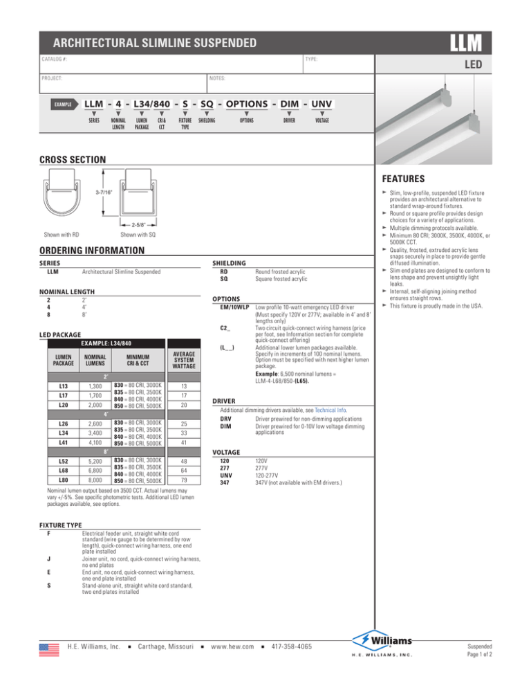
LLM ARCHITECTURAL SLIMLINE SUSPENDED CATALOG #: TYPE: PROJECT: LED NOTES: - LLM EXAMPLE t SERIES 4 t - L34/840 t t - S t - NOMINAL LUMEN CRI & FIXTURE LENGTHPACKAGECCT TYPE SQ t - OPTIONS SHIELDING t OPTIONS DIM t - DRIVER UNV t VOLTAGE CROSS SECTION FEATURES 3-7/16” 2-5/8” Shown with RD Shown with SQ ORDERING INFORMATION SERIES SHIELDING LLM RD SQ A rchitectural Slimline Suspended NOMINAL LENGTH 2 4 8 LED PACKAGE EXAMPLE: L34/840 NOMINAL LUMENS L13 1,300 L17 1,700 L20 2,000 MINIMUM CRI & CCT AVERAGE SYSTEM WATTAGE 830 = 80 CRI, 3000K 835 = 80 CRI, 3500K 840 = 80 CRI, 4000K 850 = 80 CRI, 5000K 13 2’ 17 20 4’ L26 2,600 L34 3,400 L41 4,100 830 = 80 CRI, 3000K 835 = 80 CRI, 3500K 840 = 80 CRI, 4000K 850 = 80 CRI, 5000K 25 33 5,200 L68 6,800 L80 8,000 830 = 80 CRI, 3000K 835 = 80 CRI, 3500K 840 = 80 CRI, 4000K 850 = 80 CRI, 5000K EM/10WLP Low profile 10-watt emergency LED driver (Must specify 120V or 277V; available in 4’ and 8’ lengths only) C2_ Two circuit quick-connect wiring harness (price per foot, see Information section for complete quick-connect offering) (L__) Additional lower lumen packages available. Specify in increments of 100 nominal lumens. Option must be specified with next higher lumen package. Example: 6,500 nominal lumens = LLM-4-L68/850-(L65). DRIVER Additional dimming drivers available, see Technical Info. DRV Driver prewired for non-dimming applications DIM Driver prewired for 0-10V low voltage dimming applications 41 8’ L52 Round frosted acrylic Square frosted acrylic OPTIONS 2’ 4’ 8’ LUMEN PACKAGE Slim, low-profile, suspended LED fixture provides an architectural alternative to standard wrap-around fixtures. XX Round or square profile provides design choices for a variety of applications. XX Multiple dimming protocols available. XX Minimum 80 CRI; 3000K, 3500K, 4000K, or 5000K CCT. XX Quality, frosted, extruded acrylic lens snaps securely in place to provide gentle diffused illumination. XX Slim end plates are designed to conform to lens shape and prevent unsightly light leaks. XX Internal, self-aligning joining method ensures straight rows. XX This fixture is proudly made in the USA. XX VOLTAGE 48 64 79 120 277 UNV 347 120V 277V 120-277V 347V (not available with EM drivers.) Nominal lumen output based on 3500 CCT. Actual lumens may vary +/-5%. See specific photometric tests. Additional LED lumen packages available, see options. FIXTURE TYPE F J E S E lectrical feeder unit, straight white cord standard (wire gauge to be determined by row length), quick-connect wiring harness, one end plate installed J oiner unit, no cord, quick-connect wiring harness, no end plates E nd unit, no cord, quick-connect wiring harness, one end plate installed S tand-alone unit, straight white cord standard, two end plates installed H.E. Williams, Inc. Carthage, Missouri w w w.hew.com 417-358-4065 Suspended Page 1 of 2 LLM LED ARCHITECTURAL SLIMLINE SUSPENDED PHOTOMETRY SPECIFICATIONS Housing – 20-gauge die-formed C.R.S. Shielding – Frosted, matte acrylic, round or square profile. Finish – Textured matte white polyester TGIC powder coat bonded to phosphate-free, multistage pretreated metal. All parts painted after fabrication to facilitate installation, increase efficiency, and inhibit corrosion. Electrical – High quality mid-power LED boards. Rated for 50,000 hours at 70% lumen maintenance (L70). Mounting – Suspended. 1/16” diameter adjustable steel aircraft cable and mounting hardware necessary for grid ceiling applications provided. Labels – cETLus conforms to UL STD 1598 and UL STD 8750. Certified to CAN/CSA STD C22.2 No. 250.0. Suitable for damp locations. Warranty – 5-year limited warranty, see hew.com/warranty. TEST REPORT INFORMATION XX Test Report #: 17322.0 XX Date: 05/15/13 XX Lamp Type: LED XX Rated Lumens: 4089 XX CRI: 83.1 XX CCT: 4096K Catalog #: LLM-4-L34/840-S-SQ 180° 170° 160° CANDLEPOWER DISTRIBUTION Vertical Angle 150° 140° 130° 0° 45º 90º 120° 110° 100° 90° 80° 70° 60° 50° 40° 0° 10° 20° 30° IMPORTANT: 0º 5º 15º 25º 35º 45º 55º 65º 75º 85º 90º 95º 105º 115º 125º 135º 145º 155º 165º 175º 185º Horizontal Angle 0º 1244. 1249. 1152. 995. 803. 575. 378. 228. 109. 32. 5. 0. 0. 0. 0. 0. 0. 0. 0. 0. 0. 45º 1244. 1255. 1171. 1031. 872. 703. 560. 445. 327. 238. 180. 172. 139. 114. 94. 76. 67. 50. 37. 13. 0. 90º 1244. 1258. 1177. 1046. 920. 810. 711. 608. 461. 343. 260. 241. 187. 154. 131. 107. 94. 66. 43. 25. 0. LUMEN SUMMARY Zonal Lumens 119.7 331.2 475.4 545.9 542.8 499.0 432.2 327.5 235.9 Zone Lumens 0 - 30 926. % Fixture 22.7 0 - 40 1472. 36.0 0 - 60 2514. 61.5 0 - 90 3510. 85.8 90 - 180 580. 14.2 Total Luminaire: 0 - 180 4089. 100.0 162.5 126.2 96.8 73.8 51.7 38.0 20.7 8.7 1.2 Electrostatic sensitive unit. Observe precautions when handling. FIXTURE DETAILS STANDARD HARDWARE (grid ceiling applications) BACK VIEW FEEDER/STAND-ALONE (2) ø7/8” KO For actual length see table (2) Aircraft cable mounting holes 1-7/8” NOMINAL LENGTH ACTUAL LENGTH 2’ 24-5/16” 4’ 46-7/16” 8’ 92-15/16” (2) ø1/4” Holes MOUNTING INFORMATION (center to center mounting cable) END/JOINER A A Stand-Alone Unit NOMINAL UNIT LENGTH Notes: ■■ Fixtures are provided with adjustable length aircraft cables and choice of T-bar (standard) or optional hard pan ceiling hardware, must specify. ■■ Electrical supply is brought into the feeder (or stand-alone) fixture, either as part of a row or as an individual mount unit. Joiner and end fixtures complete the row. Suspended Page 2 of 2 ROW ALIGNER DETAIL B Row-Mounted Units Row aligner CABLE MOUNT A B 2’ 23-1/4” 24 1/4” 4’ 45-3/8” 46 3/8” 8’ 91-3/4” 92 3/4 H.E . W illiams, In c. C ar t hage, Mis s our i Information contained herein is subject to change without notice. w w w.he w.c om 417- 3 5 8 - 4 0 6 5 HEW70401JL REV.08/03/16
