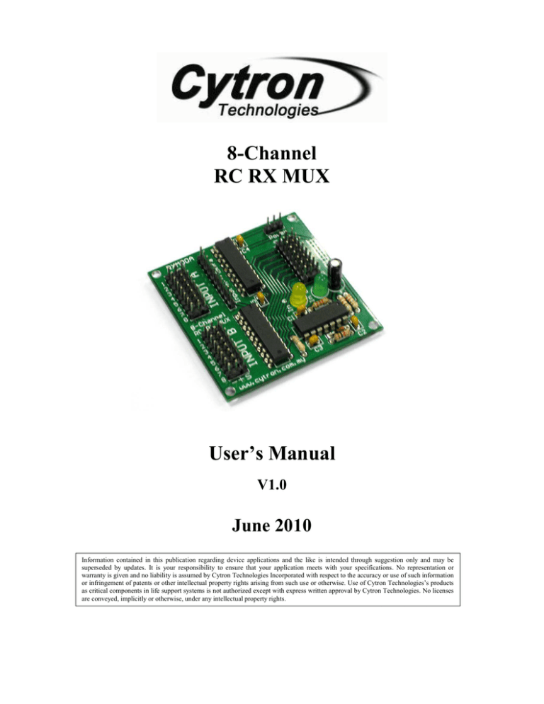
8-Channel
RC RX MUX
User’s Manual
V1.0
June 2010
Information contained in this publication regarding device applications and the like is intended through suggestion only and may be
superseded by updates. It is your responsibility to ensure that your application meets with your specifications. No representation or
warranty is given and no liability is assumed by Cytron Technologies Incorporated with respect to the accuracy or use of such information
or infringement of patents or other intellectual property rights arising from such use or otherwise. Use of Cytron Technologies’s products
as critical components in life support systems is not authorized except with express written approval by Cytron Technologies. No licenses
are conveyed, implicitly or otherwise, under any intellectual property rights.
ROBOT . HEAD to TOE
Product User’s Manual – RXM00A
Index
1. Introduction
1
2. Board or Product Layout
2
3. Getting Started
4
4. Warranty
7
Created by Cytron Technologies Sdn. Bhd. – All Rights Reserved
ROBOT . HEAD to TOE
Product User’s Manual – RXM00A
1. INTRODUCTION
The 8 Channel RC RX MUX can be used with standard hobby radio control systems
and servo controllers to allow easy switching of servo control between two signal sources
using a 8th channel of Input A as the output selector. Signal sources can come from R/C
receiver, autopilot or microcontroller that connected to Input A and Input B. Standard RC
servos are connected to the output. This makes it ideal for applications in which user has two
possible control sources and want to be able to switch between them on the fly.
For example, user could connect two RC receivers at Input A and Input B. The RC
servos are connecting to 8 channels of output. The 8th channel of Input A will decide whether
the Input A or Input B is in control, thereby setting up your own buddy-system training setup.
Another possible application would involve multiplexing between an RC receiver and a servo
controller, which will allow you to switch between autonomous and manual control of a set
of servos.
Created by Cytron Technologies Sdn. Bhd. – All Rights Reserved
1
ROBOT . HEAD to TOE
Product User’s Manual – RXM00A
2. BOARD LAYOUT
D
A
C
B
E
G
I
F
C
H
Label
A
B
C
D
E
Function
Input A
Input A - Extra
74HC541 IC
Power
Output Channel
Label
F
G
H
I
Function
Status indicator LED
Status indicator LED
CD4013 IC
Input B
A – Input A from RC receiver 1.
B – Extra pin for Input A.
C – 20 pin of Octal Buffer and Line Drivers, Three-State IC.
D – Power pin for RC RX MUX. However, user may get power from RC Receiver.
E – 8 output channel for RC servo motor.
F – Status indicator LED for Input B. If the outputs come from the Input B, only green LED
will be turn ON.
Created by Cytron Technologies Sdn. Bhd. – All Rights Reserved
2
ROBOT . HEAD to TOE
Product User’s Manual – RXM00A
G – Status indicator LED for Input A. If the outputs come from the Input A, only yellow
LED will be turn ON.
H – 14 pin of Dual D Flip Flop IC.
I – Input B from RC receiver 2
Created by Cytron Technologies Sdn. Bhd. – All Rights Reserved
3
ROBOT . HEAD to TOE
Product User’s Manual – RXM00A
3. GETTING STARTED
Switching between the two sources (Input A or Input B) is accomplished by sending
the appropriate width servo signal on the 8th channel of Input A. When a servo signal less
than 1.5ms wide is detected, signals connected to Input B are sent to the output. When no
servo signal is detected, the RC RX MUX will default connect the Input A to the Output.
Output channel 1 will read signal source from channel 1 of either Input A or Input B.
The same signal control/switching applied to the other channels.
Here is example to getting started with 8-channel RC RX MUX. 2 RC Receiver and some
servos motor are needed in using RC RX MUX.
1. Connect RC Receiver/autopilots or microcontrollers to Input A and Input B. The
channel of receiver is depends on the types or brand of the RC receiver. The 8th
channel of Input A must be connecting to a channel of RC Receiver to decide whether
the Input A or Input B is control the output.
2. Connect servos motor to the output of RC RX MUX. Output channel 1 will read
signal from channel 1 of Input A or Input B. The others output channels also will read
signal from the same input channel either Input A or Input B.
3. The power for servo motors and RC RX MUX is supply from the RC receiver.
However user may connect 6V into power pin of RC RX MUX.
4. After all the setup is finish, user may control the servo motor using Input A and Input
B depends on the signal from the 8th channel of Input A.
Created by Cytron Technologies Sdn. Bhd. – All Rights Reserved
4
ROBOT . HEAD to TOE
Product User’s Manual – RXM00A
Other signal source can be used for Input A and Input B is microcontroller. SC16A is RC
Servo motor controller which is design to control 16 independent standard RC servo motors.
Microcontroller or Servo GUI can be used to send signal to 16 channels of SC16A. These
signals from SC16A can further be connected to RC RX MUX as Input A and Input B.
Figure below shows the diagram of RC RX MUX using SC16A as receiver for both Channel
A and B. 16 channels of SC16A used as Input A and Input B. Channels 1 – 8 are Input A and
channels 9 – 16 are Input B. 8th channel of Input A uses to switch signal source (either Input
A or Input B). User may refer SC16A user manual for more details about the product and
using servo GUI.
Created by Cytron Technologies Sdn. Bhd. – All Rights Reserved
5
ROBOT . HEAD to TOE
Product User’s Manual – RXM00A
Created by Cytron Technologies Sdn. Bhd. – All Rights Reserved
6
ROBOT . HEAD to TOE
Product User’s Manual – RXM00A
4. WARRANTY
Product warranty is valid for 6 months.
Warranty only applies to manufacturing defect.
Damage caused by mis-use is not covered under warranty.
Warranty does not cover freight cost for both ways.
Prepared by
Cytron Technologies Sdn. Bhd.
19, Jalan Kebudayaan 1A,
Taman Universiti,
81300 Skudai,
Johor, Malaysia.
Tel:
Fax:
+607-521 3178
+607-521 1861
URL: www.cytron.com.my
Email: support@cytron.com.my
sales@cytron.com.my
Created by Cytron Technologies Sdn. Bhd. – All Rights Reserved
7


