White Paper
Using Pre-Emphasis and
Equalization with Stratix GX
Introduction
New high speed serial interfaces provide a major benefit to designers looking to provide greater data
bandwidth across the backplanes or when interfacing chip to chip. However high speed signaling
techniques suffer from a number of issues not seen at normal digital signaling levels. One key problem,
which applies to all transmission mediums, but particularly related to PCB layout, are frequency
dependant transmission losses, caused primarily by skin effect and dielectric loss. This transmission loss
can cause greater attenuation of the high frequency component of the signals than that of the lower
frequency component, making it difficult for the receiver to interpret the signal, thereby greatly reducing
drive length and increasing bit error rate. Two main techniques used to help overcome transmission losses
are Pre-emphasis and Receiver Equalization. These methods require extra circuitry in the transmitter and
receiver buffers to compensate for high frequency losses.
The high speed 3.125Gbps transceivers in the Stratix GX architecture incorporate pre-emphasis and
equalization circuitry within the buffers; they are dynamically controllable to ensure the user can provide
the optimum setting for their application.
This paper provides an overview of pre-emphasis and equalization and describes their operation within
Stratix GX, including some guidelines on settings for various backplane applications.
Overview of Pre-Emphasis and Equalization
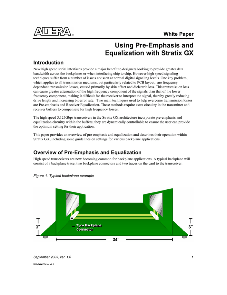
High speed transceivers are now becoming common for backplane applications. A typical backplane will
consist of a backplane trace, two backplane connectors and two traces on the card to the transceiver.
Figure 1. Typical backplane example
September 2003, ver. 1.0
WP-SGXEQUAL-1.0
1
Using Pre-Emphasis and Equalization with Stratix GX
Altera Corporation
It is often necessary for the transceiver to successfully communicate over 40” of PCB trace and two
backplane style connectors, e.g. HM-Zd connectors.
High speed signals transmitted along PCB tracks tend to suffer from high frequency attenuation, which
makes it difficult for the receiver to interpret the information. The effect is similar to a low pass filter
which decreases the gain of the high frequency signal. The main culprits are dielectric loss and skin effect,
although crosstalk and stub reflections caused by poor termination can also cause issues. These issues are
exaggerated when we consider a typical backplane application developed on FR4 PBC fabric. Fig 1 shows
a typical backplane application. The interface consists of a backplane trace, two backplane connectors and
two line cards or daughter cards.
Dielectric loss and Skin Effect
Skin Effect
The “Skin Effect” describes how high frequency currents tend to travel on the surface of the conductor,
rather than the whole cross section of the conductor. This is caused by self inductance of the material,
which increases the inductive reactance with frequency, forcing the current to travel on the surface of the
material. This reduces the effective conductive area of the trace, increasing resistance which causes the
signal to be attenuated.
As frequency increases, dielectric loss is the dominant factor in high frequency attenuation, since its effect
is proportional to frequency, whereas skin effect is proportional to the square root of frequency. Figure 2
shows the stripline loss effects against frequency.
Figure 2. 40” Stripline loss effects.
2
Altera Corporation
Using Pre-Emphasis and Equalization with Stratix GX
Dielectric loss
All PCB laminate materials have a specific dielectric constant, which will affect the impedance of the
transmission line. The value for dielectric constant can be determined by comparing its effect on the
capacitance of a conductor pair to that of a conductive pair in a vacuum. A lower dielectric constant
signifies that the material will support a longer transmission line before issues occur.
Some laminates such as FR4 will see conductivity vary with frequency. In this case dielectric loss can be
defined as a ratio of conductivity to frequency. This is known as loss Tangent. Materials with a high loss
tangent will see a deterioration of signal with frequency. FR-4 has high loss tangent, which results in a
large attenuation of the signal at high frequency. Many materials are used as PCB laminates and have both
better dielectric constraints and loss tangents; however, in volume, applications become prohibitive due to
cost. Table 1 discusses dielectric performance of various laminates and relative material costs.
Table 1 representative comparison of dielectric performance and cost
Material
FR-4
GETEK
Polyimide
Speedboard N
Rogers (RO3003)
Dielectric
Constraint
3.9 – 4.7
3.5 – 4.3
4.0 - 4.5
3.0
3.0
Loss Tangent
Value
Relative cost
to FR-4
0.02 – 0.03
0.012
0.01
0.02
0.0013
1x
1.5 x
3x
5x
6.5x
Comments
Standard process
Standard Process
Hard to process
Extra process
Hard to Process
Both dielectric loss and skin effect can cause problems of Inter-Symbol-Interference (ISI), because the
attenuation of the signal prevents it reaching full strength within its symbol time, causing it to spread into
the next signal. The effect is pattern dependent and is known as “Pattern Dependent Jitter” (PDJ) or Data
Dependent Jitter (DDJ).If a string of data remains at the same level, for example “000000” then the energy
in the signal has time to reach its peak so will be transmitted correctly; however, for a quick switching
signal such as “1010101”, full signal strength is not reached within the symbol causing a spread. “PDJ”
causes smearing of the eye diagram, signal rounding and time displacement.
A further complication is caused by dispersion, where the losses in the medium cause the different
frequency components of the signal to have different delays as they travel along the transmission line. This
further reduces signal amplitude, and adds residual error from previous bit leading to increased inter
symbol interference.
Effects of increasing Drive signal
The simple resolution would seem to be to increase the signal strength to overcome the attenuation. For
example, Stratix GX includes dynamically programmable drive strength which allows the user to select the
drive strength most suitable for the application. Unfortunately, this does not solve the problem of high
frequency roll off and the PDJ will worsen as the symbol will still not be able to achieve full strength
within its slot, and may also spread further into the next slot as a result of the increased signal level. Signal
strength also has an effect on proportional noise in the system, as the noise will increase with the signal.
The overall Power Consumption of the transceiver will also increase as the buffer is required to drive more
current.
3
Using Pre-Emphasis and Equalization with Stratix GX
Altera Corporation
Pre-emphasis
The solution is to provide a method of boosting purely the high frequency components of the signal, while
leaving the low frequency components in their original state. One way to achieve this is to use pre
emphasis.
Pre-emphasis operates by boosting the high frequency energy every time there is a transition in the data,
since this is when the most issues occur. The pre-emphasis circuitry within the Stratix GX interface acts
like a two tap Finite Response filter (FIR). The circuitry works by comparing the previously transmitted
data bit with the current data bit. If the two bits are the same level, then the current bit is transmitted at the
normal level. If the two bits are different, then the current bit is transmitted at a higher magnitude. Figure 3
demonstrates the circuitry.
Figure 3. Block implementation of Pre-emphasis circuit.
Careful design of the pre-emphasis circuit can also help to overcome dispersion. Filters are carefully
designed to ensure the frequency cutoff prevents the component of the signal spreading into the next
symbol space.
Pre-emphasis measurement
There are many different methods of measuring pre-emphasis. Although it is not important to follow a
particular measurement, it is important for the user to understand the particular definition when modeling
the system. Pre-emphasis in Stratix GX is defined as:
4
Altera Corporation
Using Pre-Emphasis and Equalization with Stratix GX
Figure 4: Waveform definition of pre-emphasis
Figure 4 shows the Altera waveform definition of pre-emphasis. The waveform describes a Differential
Signal.
The pre-emphasis circuitry within the Stratix GX architecture can be dynamically programmed to five
different levels. It is not possible to put an exact % on these levels as this is dependent on the selected
signal drive strength of the differential output. Table 2 shows example programmable pre-emphasis levels
for Stratix GX. Levels show performance for a VOD of 800mV, these values would change for alternative
VOD levels.
Table 2 Example Stratix GX Pre-emphasis levels for 800mV VOD
800mV VOD
Setting
Typical Pre-emphasis Levels
1
2
3
4
5
11%
36%
65%
100%
140%
Note: Internal termination set to 100 Ohms
Sample Eye diagrams
The eye diagram is an empirical measurement of quality of a transmitter signal. The wider the “eye”
opening is, the better the signal quality. An eye diagram also contains abundant information about signal
amplitude, rise and fall time, and jitter inter-symbol interference. Figure 5A shows an eye diagram from a
Stratix GX transceiver with pre-emphasis fully on. It can be seen that eye opening is exaggerated with the
high frequency signal and can be seen as overshoot and undershoot on the eye. Figure 5b shows the eye
5
Using Pre-Emphasis and Equalization with Stratix GX
Altera Corporation
diagram for same signal at the receiver. By the time the signal has traveled along the transmission line the
attenuating effects have removed the exaggerations and the signal can be received correctly.
Figure 5a 800mV signal with pre-emphasis,
on operating at 3.125Gbps, taken at 0”.
Figure 5b 800mV signal with pre-emphasis,
on operating at 3.125Gbps. Taken at 20”
Receiver Equalization
Receiver equalization provides functionality in the receiver to help overcome high frequency signal losses
of the transmission medium. Receiver equalization acts as a high pass filter and amplifier to the data as it
enters into the receiver. This allows the receiver to rebuild the signal and interpret it successfully. External
receiver equalization can be manufactured from external RC networks; however these require extra
components and add track stubs into the system which can have adverse effects, and they are difficult to
modify for different backplane conditions.
Stratix GX Architecture includes equalization within the receiver. The function is dynamically controllable
and can be set to 0, 20” FR4 backplane or 40” FR4 backplane. The setting is dependent on application and
environment. Receiver equalization adds up to 9db of gain at the 40” setting. Dispersion can also be
overcome within the equalizer which can be designed to cut off the unwanted frequency components, thus
stopping them from spreading into the next symbol.
Simulation Samples
It is impossible to show exact results from the Stratix GX Receiver Equalizer because it is embedded
within the device. However it is possible to simulate the results using SPICE modeling. Figure 6a shows a
simulated eye diagram into the receiver after 40 inches without pre-emphasis. Figure 6b shows the same
signal after it has passed through receiver equalization.
6
Altera Corporation
Using Pre-Emphasis and Equalization with Stratix GX
Figure 6a SPICE simulated input to Equalizer
Fig 6b SPICE Simulated output from Equalizer
It is clear that the equalization circuitry greatly improves the quality of the eye.
Using Pre-emphasis and Equalization
In many cases the system will require a combination of pre-emphasis and equalization. Functions are
complementary and can help to overcome harsh operating environments. Both also have trade offs which
need to be considered when configuring the system:
Disadvantage
Pre-Emphasis
Equalization
1) If system is susceptible to crosstalk pre
emphasis can emphasize system crosstalk as
well as signal.
1) Equalization will amplify all the high
frequency components of the signal. This
can be an issue if the signal to noise ratio
is poor
2) Pre emphasis has higher power
requirements due to the need to boost the
switching part of the signal.
3) The faster edge rates, overshoot and
undershoot associated with pre-emphasis
contribute to increased Electro-Magnetic
Interference (EMI)
It is important to select the correct values for both pre-emphasis and equalization to ensure optimum
performance. This can be achieved either via accurate system modeling using SPICE models or other link
analysis tools, or even at the debug stage using demonstrator boards.
It is necessary to select the optimum settings for both pre-emphasis and equalization. Over compensation
can cause additional issues within the system. It will add extra jitter which will close the eye making it
impossible for the receiver to interpret the information. Fig 7 shows the simulated effect of adding too
much pre-emphasis and equalization. The simulation shows a 3.125Gbps signal, after 3" FR4 PCB fabric
(VOD =4mA max Pre Emphasis and Equalization)
7
Using Pre-Emphasis and Equalization with Stratix GX
Altera Corporation
Fig 7 Effects of over compensation.
Overcoming issues in legacy systems
The explosion of high speed interfaces has led to some dilemmas because users still wish to use legacy
backplanes to reduce the cost of replacing the entire infrastructure. This means that backplanes designed to
operate at 1Gbps are now required to run at 2.5Gbps and beyond.
In some circumstances this may be possible with the combined use of pre-emphasis and equalization.
Equalization can compensate for many of the issues of the legacy backplane such as narrow tracking,
which suffers increased signal attenuation due to transmission losses. However, equalization is relatively
new as an integral part of the receiver, so it is possible that legacy cards plugged into the system will not
include equalization. This means that higher levels of pre-emphasis are required to ensure safe
communications; it is not uncommon for pre-emphasis levels in excess of 100% to be used in legacy
applications.
Pre-emphasis and Equalization in Stratix GX
Stratix GX has been developed to operate in a number of differing systems and applications. Stratix GX
provides a flexible buffer allowing the user to configure levels for pre-emphasis, equalization and drive
strength. These levels maybe programmed dynamically, making it simple to configure the transceiver for
optimum performance.
8
Altera Corporation
Using Pre-Emphasis and Equalization with Stratix GX
Dynamic control allows the user to reconfigure the signal settings in a system. This is particularly useful in
a large backplane application, where a Line Card in Slot 2 will need a completely different set of
characteristics than a Line Card in slot 21, where both are accessing the same switch card in slot 1.
Dynamic reconfiguration will allow the Line Card to reconfigure its transceiver setting, depending on the
location in the backplane.
Pre-emphasis and Equalization functions in Stratix GX can be selected to be either set during configuration
or dynamically via control pins once the device is on the board. Method of selection is made during design
in the Quartus II software tool. All transceiver configurations are made via the Quartus II Megawizard, by
using the ALTGXB Megafunction. The megafunction provides a simple interface to configure the entire
transceiver. Full details of configuration can be found in the Stratix GX Device Handbook.
Working Examples of Pre-Emphasis and Equalization with
Stratix GX
Every system and application will require different setting for pre-emphasis, equalization and drive
strength. It is therefore important to model the system environment, using accurate model for not only the
transceiver interfaces, but also for interconnect and PCB traces to ensure the system is matched. The
following table describes some results from Stratix GX characterization to show an example of the effects
of pre-emphasis and equalization. The figures can be used as an indication for design, but settings should
be based on measured and/or modeled results from the actual design.
Transceiver A
Channel Topology
Backplane Transceiver B
(Tyco)
Stratix GX
Stratix GX
Stratix GX
20”
40”
40”
Stratix GX
40”
Stratix GX
Stratix GX
rd
3 party device (with
equalizer)
rd
3 party device (without
equalizer)
Stratix GX Setting
Pre-emphasis
Equalization
Setting
Setting
0%
0%
0%
20”
40”
40”
0 to max
40”
9
Using Pre-Emphasis and Equalization with Stratix GX
Altera Corporation
Characterization has shown receiver equalization to be an effective solution when interfacing between two
Stratix GX devices, or with a third party device, (ASIC or ASSP) where the 3rd party products also
provides equalization. The Fig 8 shows simulation based on a 40” Tyco backplane, using a PRBS 10
pattern. The simulation point is between the equalization circuitry and the receive buffer. Results are
shown for various levels of pre-emphasis and equalization. Fig 8c shows the cleanest eye diagram, this was
modeled without pre-emphasis, but with maximum equalization.
Fig 8 40” Tyco backplane using a PRBS 10 pattern
10
Altera Corporation
Using Pre-Emphasis and Equalization with Stratix GX
In most cases it has been found Equalization to be an effective solution to overcoming losses within the
backplane. It has the advantage of being able to regenerate the symbol, without the need of increasing the
power requirement within the system. This can be particularly important in backplane applications where
power dissipation is difficult.
Pre-emphasis is at its most effective in systems where Stratix GX is to interface to a 3rd party device and
the 3rd party product does not include receiver equalization. In this case pre-emphasis is the only weapon
for overcoming high frequency losses.
Conclusions
Skin effect and dielectric loss can cause major attenuation to high frequency signals, impacting the success
of using high speed transceiver technology along conventional FR4 PCB fabric. The use of Pre-emphasis
and Equalization can help to overcome these issues and with careful selection can enable high speed signal
to operate in legacy systems designed to operate at much slower data rates.
The flexible transceivers in Stratix GX provide both pre-emphasis and receiver equalization, allowing them
to drive in excess of 40” FR4 PCB fabric, making it ideal for backplane design. The equalization circuitry
in particular has shown to be extremely effective in overcoming signal loss and in enabling the transceiver
to operate over longer distances. It is also a major factor in enabling the transceiver to operate in legacy
systems where the layout is being pushed to operate at higher transmission rates.
The transceiver implementation within Stratix GX can significantly help the designer to overcome signal
integrity issues.
Copyright © 2003 Altera Corporation. All rights reserved. Altera, The Programmable Solutions
Company, the stylized Altera logo, specific device designations, and all other words and logos
101 Innovation Drive
San Jose, CA 95134
(408) 544-7000
www.altera.com
that are identified as trademarks and/or service marks are, unless noted otherwise, the
trademarks and service marks of Altera Corporation in the U.S. and other countries.* All other
product or service names are the property of their respective holders. Altera products are
protected under numerous U.S. and foreign patents and pending applications, maskwork
rights, and copyrights. Altera warrants performance of its semiconductor products to current
specifications in accordance with Altera’s standard warranty, but reserves the right to make
changes to any products and services at any time without notice. Altera assumes no
responsibility or liability arising out of the application or use of any information, product, or
service described herein except as expressly agreed to in writing by Altera Corporation. Altera
customers are advised to obtain the latest version of device specifications before relying on
any published information and before placing orders for products or services.
11


