Instruction Sheet
20-Way Automotive Unsealed Hybrid
Plug Connector Assemblies 2098377-[ ] and
Cap Connector Assemblies 2098380-[ ]
Plug Connector
06 MAR 14 Rev B
Cap Connector
Terminal Cavity
(Ref)
Latch
Housing
408-10433
Terminal Cavity
(Ref)
Shroud
Housing
See Note
Alignment Channel
(5 Places)
Mating
Face
See Note
Keying
Slot
Terminal Position Assurance
(TPA) in Pre-Lock OPEN
(1ST STAGE) Position
Terminal Position Assurance
(TPA) in Pre-Lock OPEN
(1ST STAGE) Position
Alignment Rib
(5 Places)
Key
Note: When OPEN, TPA Protrudes from Housing by 4.5 mm [.177 in.] (Approx)
TERMINAL
PART NUMBER
CONNECTOR
DESCRIPTION
33012-3002
1.5-mm Tin-Plated Female
33001-3004
1.5-mm Gold-Plated Female
33000-1002
1.5-mm Tin-Plated Male
33011-0004
1.5-mm Gold-Plated Male
7116-4111-02
7114-4111-02
MOLEX product †
Plug
2
Plug
2.8-mm Tin-Plated Male
2
Cap
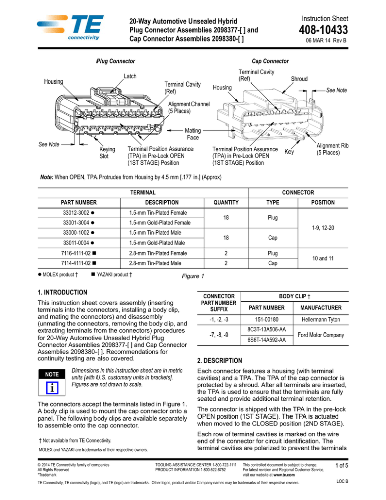
The connectors accept the terminals listed in Figure 1.
A body clip is used to mount the cap connector onto a
panel. The following body clips are available separately
to assemble onto the cap connector.
MOLEX and YAZAKI are trademarks of their respective owners.
10 and 11
Figure 1
Dimensions in this instruction sheet are in metric
units [with U.S. customary units in brackets].
Figures are not drawn to scale.
† Not available from TE Connectivity.
POSITION
1-9, 12-20
2.8-mm Tin-Plated Female
YAZAKI product †
© 2014 TE Connectivity family of companies
All Rights Reserved
*Trademark
18
Cap
This instruction sheet covers assembly (inserting
terminals into the connectors, installing a body clip,
and mating the connectors) and disassembly
(unmating the connectors, removing the body clip, and
extracting terminals from the connectors) procedures
for 20-Way Automotive Unsealed Hybrid Plug
Connector Assemblies 2098377-[ ] and Cap Connector
Assemblies 2098380-[ ]. Recommendations for
continuity testing are also covered.
i
TYPE
18
1. INTRODUCTION
NOTE
QUANTITY
CONNECTOR
PART NUMBER
SUFFIX
PART NUMBER
MANUFACTURER
-1, -2, -3
151-00180
Hellermann Tyton
-7, -8, -9
BODY CLIP †
8C3T-13A506-AA
6S6T-14A592-AA
Ford Motor Company
2. DESCRIPTION
Each connector features a housing (with terminal
cavities) and a TPA. The TPA of the cap connector is
protected by a shroud. After all terminals are inserted,
the TPA is used to ensure that the terminals are fully
seated and provide additional terminal retention.
The connector is shipped with the TPA in the pre-lock
OPEN position (1ST STAGE). The TPA is actuated
when moved to the CLOSED position (2ND STAGE).
Each row of terminal cavities is marked on the wire
end of the connector for circuit identification. The
terminal cavities are polarized to prevent the terminals
TOOLING ASSISTANCE CENTER 1-800-722-1111
PRODUCT INFORMATION 1-800-522-6752
This controlled document is subject to change.
For latest revision and Regional Customer Service,
visit our website at www.te.com
TE Connectivity, TE connectivity (logo), and TE (logo) are trademarks. Other logos, product and/or Company names may be trademarks of their respective owners.
1 of 5
LOC B
408-10433
from being inserted upside-down. When inserted, the
terminal deflects a retention finger, locking the terminal
into place.
The housing features a key and alignment channels
(plug connector) or keying slot and alignment ribs (cap
connector). The cap connector features a hold-down
retainer, which holds the optional body clip. When mating
the connectors, the alignment slots and alignment ribs
properly align the connectors. See Figure 1.
the terminal with the desired terminal cavity, orienting
the terminal so that the alignment tab located on the
top of the terminal box (for 1.5-mm terminals) or the
orientation tabs located on the sides of the terminal
box (for 2.8-mm terminals) is facing the top of the
terminal cavity. The orientation of the terminal for
the top row is the opposite of the bottom row.
3. Push the terminal straight into the terminal cavity
until it stops (there will be an audible “click”).
CAUTION
3. ASSEMBLY
!
3.1. Insert Terminals
The following procedure assumes that the terminals
have been properly crimped. Refer to Figure 2, Detail A
for inserting 1.5-mm terminals and Detail B for inserting
2.8-mm terminals into the plug and cap connectors.
Proceed as follows:
1. Ensure that the TPA of the connector is in the
OPEN position as shown in Figure 1. If it is not,
insert the tip of a small screwdriver into one of the
removal slots of the housing (shown in Figure 8),
and pry the TPA until it is in the OPEN position.
The TPA should protrude from the housing by
approximately 4.5 mm [.177 in.]. DO NOT remove
the TPA completely from the housing. For the cap
connector, note that even though the TPA protrudes
from the housing, it is recessed in the shroud.
2. Grasp the wire of the terminal approximately
20 mm [.75 in.] behind the insulation barrel of the
terminal, then at the wire end of the connector, align
DO NOT force the terminal into the terminal cavity.
If there is resistance or the wire “buckles,” pull the
terminal out, ensure proper orientation, and
re-insert the terminal.
4. After all terminals are inserted, push the TPA into
the housing until it stops. The TPA should be flush
with the housing (CLOSED position). See Figure 3.
CAUTION
Make sure to AVOID pushing the tips of the
terminals.
!
3.2. Test for Continuity
It is recommended using a continuity test fixture that
will not cause damage to the terminals. Consult the
continuity test fixture manufacturer for acceptable
force for probing.
From the mating face of the plug connector, insert the
test probe into the access window of the terminal to be
tested. See Figure 4.
Detail A — Inserting 1.5-mm Terminals
Plug Connector
Cap Connector
Top Row
Top Row
Insulation Barrel
of Terminal
Wire
Wire End of
Connector
Bottom Row
Wire
Insulation Barrel
of Terminal
Wire End of
Connector
Bottom Row
Figure 2 (Cont’d)
Rev B
2 of 5
408-10433
Detail B — Inserting 2.8-mm Terminals
Plug Connector
Cap Connector
Top Row
Top Row
Wire End of
Connector
Wire
Insulation Barrel
of Terminal
Bottom Row
Wire
Wire End of
Connector
Bottom Row
Insulation Barrel
of Terminal
Figure 2 (End)
Moving TPA to CLOSED Position
CAUTION
!
To avoid damage to the terminal, MAKE SURE that
the probe does not apply excessive force to the tip
of the terminal.
Plug Connector
Continuity Testing
Mating Face
Access Window
(1 per Terminal)
for Top Row
TPA Flush with Housing
Cap Connector
Mating Face
Mating Face of
Plug Connector
Access Window
(1 per Terminal)
for Bottom Row
Figure 4
3.3. Install Body Clip (Optional)
TPA Flush with Housing
(But Recessed in Shroud)
Figure 3
Rev B
1. Align the body clip with the mating face of the cap
connector so that the latch faces the end of the
hold-down retainer of the cap connector. See Figure
Figure 5, Detail A.
2. Slide the body clip onto the hold-down retainer
until it is fully seated (there will be an audible or
haptic “click”). See Figure Figure 5, Detail B.
3 of 5
408-10433
Mating Connectors
Installing Body Clip (Optional)
Detail A
Detail A
Latch of
Body Clip
Wire End of
Cap Connector
Key of
Cap Connector
Keying Slot of
Plug Connector
Hold-Down Retainer
of Cap Connector
Detail B
Detail B
Latch of
Plug Connector
Body Clip Fully Seated
Shroud of
Cap Connector
Figure 5
Figure 6
3.4. Mate Connectors
1. Align the mating faces of the connectors so that
the key of the cap connector faces the keying slot of
the plug connector. See Figure Figure 6, Detail A.
Removing Body Clip
Mating Face of
Cap Connector
2. Push the connectors together so that the
alignment ribs enter the alignment slots and until the
latch of the plug connector engages the shroud of
the cap connector (there will be an audible “click”).
See Figure 6, Detail B.
Rotate Screwdriver
4. DISASSEMBLY
4.1. Unmating Connectors
Depress the latch of the plug connector (shown in
Figure 6), and simultaneously pull the connectors apart.
4.2. Removing Body Clip
1. From the mating face of the cap connector, slide
the tip of a flat blade screwdriver into the hold-down
retainer so that it is under the latch of the body clip.
See Figure 7.
2. Rotate the screwdriver so that the latch of the
body clip is free from the hold-down retainer.
3. Slide the body clip out of the hold-down retainer.
Rev B
Tip of Screwdriver
Latch of Body Clip
Figure 7
4.3. Extracting Terminals
1. Remove the TPA from the housing of the
connector as follows:
For the plug connector, from the mating face,
insert the tip of a small screwdriver into one of the
removal slots, and pry the TPA out and away
from the housing. Refer to Figure 8, Detail A.
For the cap connector, from the wire end, insert
the tip of a small screwdriver into one of the
4 of 5
408-10433
removal slots, rotate the screwdriver to pry the
TPA latch toward the wires, then push the TPA
out of the mating face of the connector and away
from the housing. Refer to Figure 8, Detail B.
Removing TPA (for Extracting Terminals)
Detail A
Detail A — Plug Connector — Bottom Row Shown
Mating Face of Connector
Rotate
Screwdriver†
Tip of Screwdriver
in Removal Slot
of Housing
Pry TPA
Out of
Housing
Mating Face of
Cap Connector
Extracting Terminals
Tip of Screwdriver
in Terminal Cavity
of Terminal to Be
Removed
Housing
Retention Finger
Holding Terminal
Push Wire to
Release Pressure
Pull Wire to
Remove Terminal
† Rotate Screwdriver Opposite Direction for Top Row
Removal Slot of
Housing (Ref)
Mating Face of
Plug Connector
Detail B
Detail B — Cap Connector — Top Row Shown
Housing
Retention Finger
Holding Terminal
Mating Face of Connector
Rotate
Screwdriver†
Tip of Screwdriver
in Removal Slot
of Housing
Rotate
Screwdriver to
Pry TPA Latch,
Then Push TPA
Out of Housing
Removal Slot of
Housing (Ref)
Wires
Tip of Screwdriver
in Terminal Cavity
of Terminal to Be
Removed
Push Wire to
Release Pressure
Pull Wire to
Remove Terminal
† Rotate Screwdriver Opposite Direction for Bottom Row
Figure 9
Figure 8
2. At the mating face of the connector, insert the
tip of a flat blade screwdriver into the terminal cavity
of the terminal to be removed until it stops. See
Figure 9, Detail A (plug connector) and Detail B (cap
connector).
3. Holding the screwdriver in place, gently push the
wire of the terminal to be removed toward the
housing until it stops (this will release the pressure
on the terminal).
4. Rotate the screwdriver toward the terminal to lift
the housing retention finger away from the terminal.
While holding the screwdriver in position, pull the
wire until the terminal is released, then pull the
terminal straight out of the terminal cavity.
5. Pull the screwdriver out of the connector.
6. Insert a new terminal according to Paragraph 3.1,
and test the terminal following the recommendations
given in Paragraph 3.2.
Rev B
7. Re-install the TPA into the housing of the connector
and move it to the CLOSED position as follows:
a. From the mating face of the connector, align
the terminal cavities of the TPA with the tips of the
terminals.
b. Carefully, slide the TPA into the connector
until it stops. Be careful not to bend any of the
terminals. If a terminal is bent, replace it.
5. REPLACEMENT AND REPAIR
The connectors and terminals are not repairable.
DO NOT use any defective or damaged connectors or
terminals. DO NOT re-use a terminated terminal by
removing the wire.
6. REVISION SUMMARY
• Changed position information in table in Figure 1
5 of 5


