Hall Coefficient of Germanium - Wooster Physics
advertisement

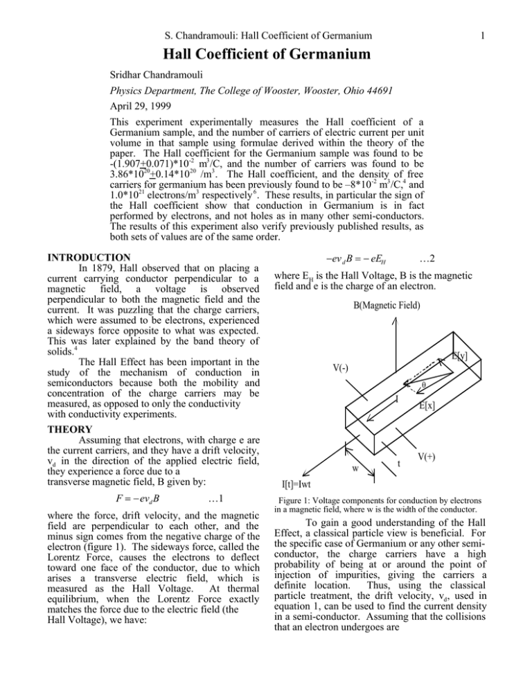
S. Chandramouli: Hall Coefficient of Germanium 1 Hall Coefficient of Germanium Sridhar Chandramouli Physics Department, The College of Wooster, Wooster, Ohio 44691 April 29, 1999 This experiment experimentally measures the Hall coefficient of a Germanium sample, and the number of carriers of electric current per unit volume in that sample using formulae derived within the theory of the paper. The Hall coefficient for the Germanium sample was found to be -(1.907+0.071)*10-2 m3 /C, and the number of carriers was found to be 3.86*1020+0.14*1020 /m3 . The Hall coefficient, and the density of free carriers for germanium has been previously found to be –8*10-2 m3 /C,4 and 1.0*1021 electrons/m3 respectively 6 . These results, in particular the sign of the Hall coefficient show that conduction in Germanium is in fact performed by electrons, and not holes as in many other semi-conductors. The results of this experiment also verify previously published results, as both sets of values are of the same order. INTRODUCTION In 1879, Hall observed that on placing a current carrying conductor perpendicular to a magnetic field, a voltage is observed perpendicular to both the magnetic field and the current. It was puzzling that the charge carriers, which were assumed to be electrons, experienced a sideways force opposite to what was expected. This was later explained by the band theory of solids.4 The Hall Effect has been important in the study of the mechanism of conduction in semiconductors because both the mobility and concentration of the charge carriers may be measured, as opposed to only the conductivity with conductivity experiments. THEORY Assuming that electrons, with charge e are the current carriers, and they have a drift velocity, vd in the direction of the applied electric field, they experience a force due to a transverse magnetic field, B given by: F = −evd B …1 where the force, drift velocity, and the magnetic field are perpendicular to each other, and the minus sign comes from the negative charge of the electron (figure 1). The sideways force, called the Lorentz Force, causes the electrons to deflect toward one face of the conductor, due to which arises a transverse electric field, which is measured as the Hall Voltage. At thermal equilibrium, when the Lorentz Force exactly matches the force due to the electric field (the Hall Voltage), we have: −ev d B = − eEH …2 where EH is the Hall Voltage, B is the magnetic field and e is the charge of an electron. B(Magnetic Field) E[y] V(-) θ I w t E[x] V(+) I[t]=Iwt Figure 1: Voltage components for conduction by electrons in a magnetic field, where w is the width of the conductor. To gain a good understanding of the Hall Effect, a classical particle view is beneficial. For the specific case of Germanium or any other semiconductor, the charge carriers have a high probability of being at or around the point of injection of impurities, giving the carriers a definite location. Thus, using the classical particle treatment, the drift velocity, vd , used in equation 1, can be used to find the current density in a semi-conductor. Assuming that the collisions that an electron undergoes are S. Chandramouli: Hall Coefficient of Germanium completely random, the current density, j is: by moving into the hole. It appears like the hole is moving in the opposite direction of the j = −env d …3 electrons and thus, positive charges or holes are where e is the charge of an electron, and n is the said to carry the current. Holes may be introduced into a number of electrons per unit volume. The drift germanium sample by careful injection of velocity used in equation 1 is not a very impurities, the process called doping. This sheds convenient parameter. Using equations 2 and 3, light on the possibility of positive current carriers, we can derive a convenient expression for the and thus some Hall Coefficient are positive, Hall Voltage in terms of the current density. because of conduction by positive holes in the E V t valence bands. Equation 5 may be modified to RH = H = ( H ) …4 include a positive charge instead of the –e in the jB I B denominator. Thus, the sign of the Hall where VH is the average Hall Voltage, or simply Coefficient may be used to discover the nature of the Hall Voltage divided by the width across the charge carriers. which the voltage was measured (the width of the sample). The other parameters are given sense by Experimental Setup & Procedure To calculate the Hall Coefficient of figure 1, and previous equations. Germanium, the power supply (Hewlett Packard The applied electric field, and the 6216C) sends a current through the Ge sample, transverse electric field created by the magnetic while the permanent magnet provides a strong field give a resultant electric field which is not magnetic field perpendicular to the direction of parallel to the current. The angle θ, which the current. A voltmeter (Keithley 197 separates the current from the resultant electric Autoranging Microvolt DMM) is connected field (figure 1), enables the derivation of a perpendicular to both, the direction of flow of the formula for the Hall Coefficient, already stated in current and the magnetic field. This is used to equation 4, in terms of the charge of the carrier, make observations of the Hall Voltage, An and the charge density. But in fact equation 4 is a ammeter (Tektronix CDM250 Digital Multimeter) very simplified view of the system which involves many simplifying assumptions regarding the is connected to the DC power supply to make collisions of the electrons. In reality, the measurements of current flowing through the probability of collision depends in a complicated germanium sample. A traveling Microscope (Gaertner Scientific Corporation), and a gauss way on both the initial and final states.6 When meter (Applied Magnetics Laboratories) complete this is accounted for the equation reduces to: the equipment list. 3π 1 The DC power supply has control over the RH = …5 current passing through the sample. The current 8 n(−e) may be varied by directly changing the current, or Some Hall Coefficients are found to be by varying the voltage that drives the current. positive, conflicting with the electron theory of The instruments are very sensitive to change in conduction. The band theory of solids is essential either parameter, and extreme care must be taken to explain the deflection of current carriers in to attain the desired level of current through the semi-conductors like Germanium. When the Hall Ge sample. Once a desired current has been Effect was first observed, the apparent opposite achieved, a transverse voltage reading is made at deflection of the electrons, which were considered the voltmeter. The desired current was attained in the only current carriers, was puzzling. This was different runs of the experiment, by alternately resolved by the band theory of solids in the early keeping the current and the voltage constant, and part of this century. Valence electrons occupy a varying the other parameter. complete set/band of states that spans a finite First, the experiment was conducted range of energies; therefore no electron may be without any magnetic field. Theoretically, there moved to any other valence state without violating should be no transverse voltage as current carriers Pauli’s Exclusion Principle, so valence electrons would not have deflected. Start the experiment at are rigid and can carry no current. In metals, the 15 mA, and make readings of the transverse bands overlap and so electrons move freely from voltage for successive decrements in the current, the upper valence bands to the lower conduction down to 1mA, or even lower. Then slowly bands and thus conduct. When an electron from a increase the current back to 15 mA once again and filled valence band is removed, there is now a check for reproducibility of the data. The hole in the valence band for other electrons to experiment is repeated under the influence of the move into, and they may now conduct electricity 2 S. Chandramouli: Hall Coefficient of Germanium known magnetic field. The field is then inverted with the magnetic field are thus also and the experiment redone yet again. systematically erred by the same amount. The strength of the magnetic field and the Therefore, in graph 1, the voltage is non-zero dimensions of the Ge sample are the other even for a zero magnetic field. In graph 1, the measurements required. To measure the strength error bars are constant values. The negative B of the magnetic field, the probe of the Gauss field merely signifies an opposite orientation of meter is introduced exactly in the middle of the north and south poles. space between the two poles, and a series of To correct for the error, the voltage readings are made, because the field is very readings in the absence of any magnetic field are variable. The average value of the readings is systematically forced to zero, and adjustments are used in the determination of the Hall Coefficient. accordingly made to the Hall Voltage readings. The dimensions of the Ge sample are measured The values of the zero magnetic field voltages are using a traveling microscope. Only the thickness subtracted from both sets of Hall voltages. To of the sample is required in the determination of calculate the Hall Coefficient of germanium, we the Hall Coefficient. Nevertheless, measurements look to equation 4. One method that can be were made of all the dimensions of the sample. employed to measure the Hall Coefficient of Since the Ge sample is set within a frame and germanium is computing the Hall Coefficient for should not be disturbed, its thickness is measured each of the values of current, and then using the with a traveling microscope. The front and back mean and standard deviation of all those values. end of the sample are focussed one after the other But there is a more elegant method. The factor and the distance moved by the calipers recorded. VH/I is the slope of the plot of the current and the Using simple trigonometric functions, the Hall Voltage. Therefore, a line can be fitted to the thickness is easily estimated. values of the Hall Voltage at various values of current, and the slope of this line may be used, Data, Error, Error Propagation & Analysis with the error in fit (standard deviation), to The magnetic field was measured as along calculate the Hall Coefficient (graph 2). The (171.7+1.3)*10-3 Tesla, which is the SI units for measurement of the magnetic field, and the magnetic fields. A conversion factor of 10 4 was thickness of the germanium sample is conducted used to convert between Gauss and Tesla. The as described in the and their errors are dimensions of the Ge sample were measured to be simply a standardprocedure, deviation of a series of (4843.3+5.8)*10-6 m (length), (483.0+2.6)*10-5 m observations. These steps accounts for all the (width), and (1815.0+6.5)*10 -6 m (thickness). random error involved in the observations. 0 -30 -40 Voltage (milliVolts) -20 B=((171.7+1.3)e-3) Tesla 20 B=0 10 0 B=((-171.7+1.3)e-3) Tesla -10 B=(171.7+1.3)e-3 Tesla VH=((-3.1+1.0)e-1)-(1.81+0.01) I Voltage (milliAmps) -10 B=0 VH=((-1.4+1.2)e-1)-((179.8+1.3)e-2) I B=(-171.7+1.3)e-3 Tesla -50 -20 -60 2 4 6 8 10 12 14 Current (milliAmps) Graph 1: Transverse (Hall) Voltage plotted against the longitudinal current, uncorrected for systematic errors. The opaque squares and circles are voltages for opposite orientations of the magnetic field, while the crosses are voltages in the presence of no magnetic field. Systematic errors, probably due to faulty calibration, causes the voltage recorded without the magnetic field to be consistently non-zero. The transverse voltage should be zero in the absence of a magnetic field because none of the charge carriers are deflected, and hence no Hall Voltage can be set up. The Hall Voltage readings 2 4 6 8 10 12 14 Current (milliVolts) Graph 2: Current plotted against voltage, corrected for systematic error, such that there is no voltage reading for B=0. Straight lines are fitted to the data. The markers are consistent with graph 1. The slope of both the lines (current plotted against Hall voltage) for the different orientations of the magnetic field, are similar. Since the values are so consistent, the average value of the two slopes (VH/I) is used and the errors of the individual line fits also propagate as averages, since this error is 3 S. Chandramouli: Hall Coefficient of Germanium greater than simply the standard deviation of the References 1 two consistent slopes. The Hall Coefficient of Pugh, Emerson, M., Pugh, Emerson, W., germanium can thus be calculated: Principles of Electricity and Magnetism, (Addison-Wesley Publishing Company, Inc., 3 −2 −2 m 1960). …6 R H = −1.907*10 ± 0.071*10 2 C Feynman, Richard, P., The Feynman Lectures on Physics, Volume III, (Addison-Wesley Publishing On observing the sign of the Hall Company, Inc., 1965). Coefficient of germanium, it can be concluded 3 Junior Independent Study Lab Manual, Spring, that the charge carriers in Ge are in fact electrons. -2 1999, (Unpublished). The above value compares favorably with –8*10 4 Lerner, Rita, G., Trigg, George, L., Concise m3 /C, reported by Lerner et.al.4 The negative sign Encyclopedia of Solid-State Physics, (Addisonmay arise also imply due to the connection of the Wesley Publishing Company, Inc., 1983). voltmeter. Keeping track of the magnetic fields 5 Seitz, Frederick, The Modern Theory of Solids, therefore becomes very important. First Edition, (McGraw-Hill Book Company, Inc., Further, the density of the electrons is New York & London, 1940). calculated using equation 5. The Hall Coefficient 6 Shockley, William, Electrons and Holes in for germanium is known along with its associated Semiconductors, (D. Van Nostrand Company, errors, Therefore, the density of conducting Inc.,1950. electrons in Ge is: n = 3.861*10 20 ± 0.14*10 20 electrons/m 3 …7 The density of the current carriers is also consistent with values reported earlier. Shockely6 reported a value of 1.0*1021 electrons/m3 , and Lerner et.al4 reported a value of the apparent number of free electrons per atom as 1.7*10-9. To convert to the units used in this paper, (electrons/m3 ) we have to find the number of atoms per unit volume for Ge. We find that there are 4.4*10 28 atoms/m3 , and therefore, the density of free electrons is: 4.4*1028 atoms/m3 * 1.7*10-9 electrons/atom = 7.48*1019 electrons/m3 . Conclusion The Hall Effect is important because it enables us to make measures of mobility and concentration, and gives insight into the mechanism of conductivity in semi-conductors. The Hall Coefficient and the density of carriers in Ge are well known quantities, and have been verified in this paper, given experimental limitations, with values of the same order. Also, it is established that the primary charge carriers are electrons in our sample of germanium. In some cases, conduction occurs in both the valence bands and the conduction bands. Therefore, electrons and positive holes simultaneously carry current, though in the Ge sample used in the experiment, the electrons predominate over the positive holes. If the experiment were conducted at low temperatures, and a variable magnetic field used, the Quantum Hall Effect could have been observed. This is characterized by a step function that arises when the resistivity of the sample is plotted against the varying magnetic field. _______________________________________ 4


