Technote 42 - Modbus RS-485 Timing Issues
Author: Michael Hewitt (acknowledgments to Stephen Herzog)
This document discusses communication timing effects on Data Acquisition Servers (DAS) AcquiSuite
EMB A8810, AcquiSuite A8812, and AcquiLite EMB A7810 (using Modbus/TCP).
Optimal Settings
Timing considerations are an important aspect of installations and optimal DAS configuration. The
specifics are very unique to each installation. Many factors affect timing, including:
• number of monitored devices
• amount of data in responses from monitored devices
• response time of monitored devices
• hardwired-only, or hardwired and wireless devices
• baud rate or baud rates
• log interval
• log upload cycle
Query and Response Time
The DAS continuously scans the Modbus loop for all possible addresses, which is about 250 according
to the limits of the Modbus language. For more details about Modbus, see modbus.org. Regardless of
how many devices you may have actually connected, in order to properly detect changes in the bus
loop, the DAS continuously scans the entire list, one device at at time. The scanning process basically
consists of a DAS query and a device reply. Each query takes a certain amount of time, as the DAS
toggles bits of information onto the Modbus loop at a certain speed. The wire itself has some delay,
especially if the “wire” is TCP/Modbus or a radio transceiver pair (like ModHoppers), in which the
query gets processed by another device, transmitted, received, and then processed by another device
which translates back into Modbus. Each device adds some delay. Once the Modbus query arrives at a
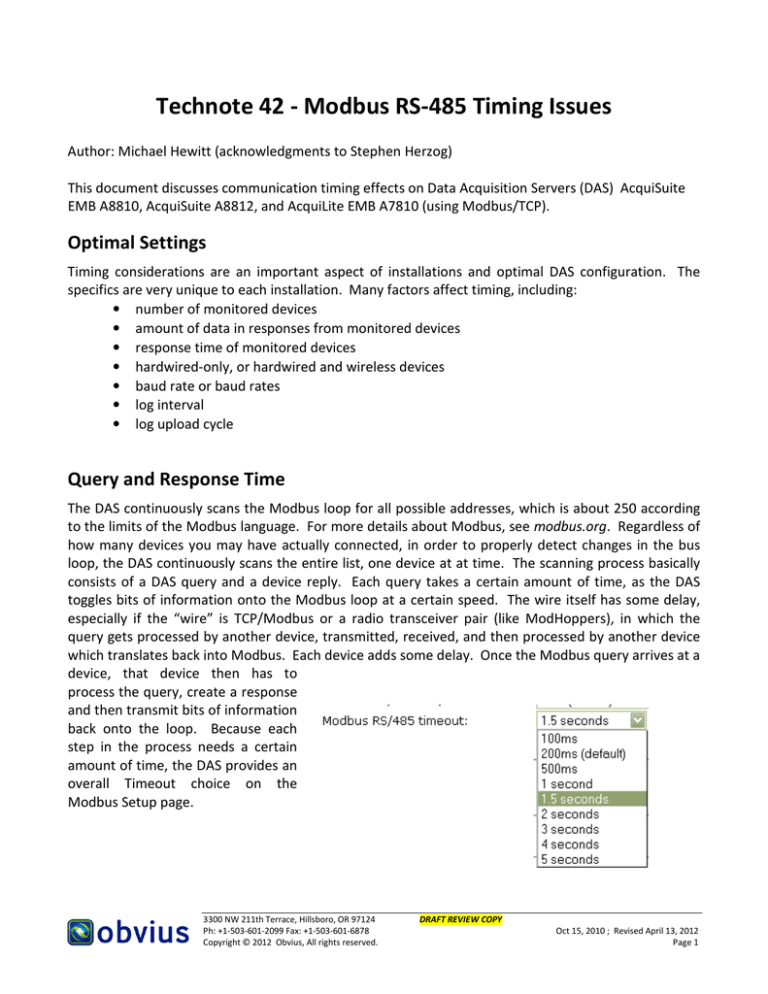
device, that device then has to
process the query, create a response
and then transmit bits of information
back onto the loop. Because each
step in the process needs a certain
amount of time, the DAS provides an
overall Timeout choice on the
Modbus Setup page.
3300 NW 211th Terrace, Hillsboro, OR 97124
Ph: +1-503-601-2099 Fax: +1-503-601-6878
Copyright © 2012 Obvius, All rights reserved.
DRAFT REVIEW COPY
Oct 15, 2010 ; Revised April 13, 2012
Page 1
Timing Example
Pictured is an idealized visual representation of that timing, with some approximate times:
~20mS
DAS
issues
query
~0 to ?
wire
delay
~40mS
device
receives
query
~0 to ?
device
reponds
wire
delay
DAS
receives
response
TIME
Given this example and a single device, if the wire delay was 20mS, then the total time is:
20ms + 20mS + 40mS + 20mS = 100mS
Too Little Time, Too Much Time
Using the Timing Example, consider what would happen if the DAS only waited 50mS for the response
from the start of its query. According to the illustration, the device would just be processing the
received query from the DAS at that moment. In that scenario, the DAS would report that the device
was in an error condition since it never got a device response.
Note that the example also illustrates that variances exist, such as delays on a TCP gateway (which
could be the “wire”) in the illustration. Typically adding more time to the Timeout reduces the
probability that the variations cause data loss because of those delays. So a reasonable time added to
pad the example timeout might put it at 150mS.
So if 150mS is good, then why is 1500mS not better? Why is 15,000mS not better still? At the other
extreme, waiting too long for responses causes other types of problems, including:
Latency delays prevent quick visibility of live device or sensor information. As you watch an
actual event in real time, like a temperature change, rather than seeing an immediate
difference on a browser page of the DAS, it displays much later.
Since the DAS polls all possible devices, it may run out of log cycle time to read them all. A big
timeout delay, such as 5 seconds (5000mS) becomes a big total time to check all of them.
Roughly calculated, this is
250 x 5 seconds = 1250 seconds = approx. 20 minutes.
So despite the available CPU speed of the DAS and devices, theoretically each device would
only report 3 times an hour. Stated another way, you may have to wait 20 minutes to see
updated information on a device which you just adjusted. Additionally, if the time exceeds the
log cycle, the information may only update every other cycle.
3300 NW 211th Terrace, Hillsboro, OR 97124
Ph: +1-503-601-2099 Fax: +1-503-601-6878
Copyright © 2012 Obvius, All rights reserved.
DRAFT REVIEW COPY
Oct 15, 2010 ; Revised April 13, 2012
Page 2
Additional Factors
Device Response Time
Because a device may be very simple or very complex, the amount of time needed to gather that data
and to communicate that data may vary. The more data, the longer time needed to send that data.
Some requirements exist within the Modbus protocol. Some devices have been known to exceed
recommended response times, in some cases taking over a second.
Intermediate devices also transfer information from groups of devices, so they may need additional
timeouts. such as TCP gateways or ModHoppers For example, it is recommended to add 500mS for
each wireless hop.
Complex Timing Example
ModHopper
B
RF Ch.1
DAS
ModHopper
C
RF Ch.2
ModHopper
A
RF Ch.1
Meter
ModHopper
D
RF Ch.2
Solid lines represent RS-485 wiring Dashed lines represent radio comms
The Complex Timing Example is an illustration of a much more complex timing situation, with some
environmental or device effects introducing considerable delays. ModHoppers B and C are assumed
to be ForceMaster/ForceSlave. ModHoppers each have their own configurable Timeout for devices
wired to them. In this scenario, the various timeouts may be:
• DAS
2Sec-5Sec
• MH A
N/A
• MH B
1Sec
• MH C
N/A
• MH D
200mS*
* The value of 200mS is a typical value. If the meter was an Onicon SYSTEM-10, then ModHopper D
would possibly need a Timeout of 500mS to 1000mS. If the meter was a GE kV2™, it would possibly
need up to 2 Seconds. Other hardware may require similar times.
This could be further complicated if the DAS shown was also used as a Modbus/TCP gateway to
another DAS. On the other DAS, any additional network delays would also need to be added to the
Timeout used on the DAS shown in the example.
Note that ModHopper transmission times vary as they encounter changing radio conditions.
3300 NW 211th Terrace, Hillsboro, OR 97124
Ph: +1-503-601-2099 Fax: +1-503-601-6878
Copyright © 2012 Obvius, All rights reserved.
DRAFT REVIEW COPY
Oct 15, 2010 ; Revised April 13, 2012
Page 3
DAS Features
Fortunately, the AcquiSuite EMB A8810, AcquiSuite A8812, and AcquiLite EMB A7810 (using
Modbus/TCP) have valuable optimization techniques. For example, the timeout only regards devices
which do not respond. Once a device responds, waiting is no longer necessary and the exchange of
data drives the remaining time devoted to that device. Other optimizations exist, such as
prioritization.
The DAS configuration includes Modbus Setup, which has multiple choices. An optimal site is one with
mutual hardware communication values, such as a single baud rate. The optimizations provided on
that page should be considered regarding a particular site.
Discovering Query and Response Time
The DAS provides a very handy way to help find
that perfect balance between too little time and
too much time. On the Device List page, click on
the “stats” link. The RTT column on the right side
will the display the last-known Round Trip Time
(RTT) of each device. In the Timing Example
illustration, that device would likely show round
trip times around 100mS in that column.
To best tune the system, watch the times and communications health for all the devices, and set the
timeout to something slightly larger than the longest RTT. Try it for a while that way, and if no devices
go into Error, it is fine. Aside from errors, also look at the ratio of Sent (queries) and Received (device
responses). Many Sent but fewer or no Received, may indicate the need for a longer timeout. The top
row in the above picture shows such a 2:1 difference. If using ModHoppers, view the ModHoppers
page, under Wireless, which also has timing information including number of wireless hops.
Advanced Techniques
In addition to the optimizations in the AcquiSuite EMB A8810, AcquiSuite A8812, and AcquiLite EMB
A7810 (using Modbus/TCP), when used with care certain techniques may help sites with problematic
timing. When in doubt, use defaults or contact Obvius Support.
• Disable the Modbus Setup option Search for Modbus devices. Note that later adding a device
will require enabling that option.
• If not wired to pulse meters, configure a ModHopper Data log points option to None.
• Set the Modbus Setup option Modbus RS/485 debug information to Full Debug, and enable
debugging on the System Log Files page. View the Debugging Messages log, then disable
debugging again. The log shows timing of Modbus communication events.
• In a similar way, set the level to Transactions for a while, to watch for unexpected traffic such
as Modbus/TCP queries to the DAS.
3300 NW 211th Terrace, Hillsboro, OR 97124
Ph: +1-503-601-2099 Fax: +1-503-601-6878
Copyright © 2012 Obvius, All rights reserved.
DRAFT REVIEW COPY
Oct 15, 2010 ; Revised April 13, 2012
Page 4

