REPAIR INSTRUCTIONS
Issued by ROBERT BOSCH (AUSTRALIA) PTY. LTD.
A.C.N. 004 315 628
Incorporated in Victoria
SUBJECT:
File:
Section:
Bulletin No.
Page:
Date:
Supersedes:
ABSP
GMH
0003
1 of 2
May, 1998
VT ABS 5.3 4S/3K
This document is applicable to VT-ABS only equipped vehicles as these items differ from the
ABS/TCS equipped vehicles.
The references of the hydraulic schematics in the repair instructions ABSP/GHM/0001, are
applicable to the VT ABS only 5.3 system.
Use the repair instructions ABSP/GHM/0002 for fault diagnosis of the relevant fault code.
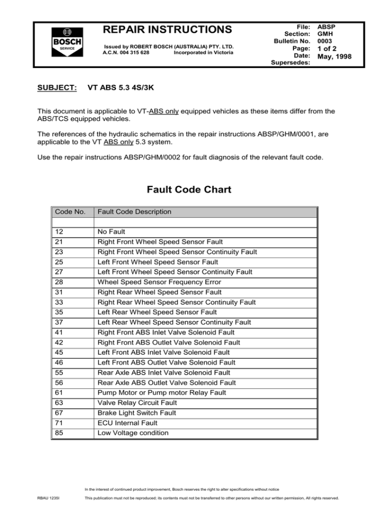
Fault Code Chart
Code No.
Fault Code Description
12
No Fault
21
Right Front Wheel Speed Sensor Fault
23
Right Front Wheel Speed Sensor Continuity Fault
25
Left Front Wheel Speed Sensor Fault
27
Left Front Wheel Speed Sensor Continuity Fault
28
Wheel Speed Sensor Frequency Error
31
Right Rear Wheel Speed Sensor Fault
33
Right Rear Wheel Speed Sensor Continuity Fault
35
Left Rear Wheel Speed Sensor Fault
37
Left Rear Wheel Speed Sensor Continuity Fault
41
Right Front ABS Inlet Valve Solenoid Fault
42
Right Front ABS Outlet Valve Solenoid Fault
45
Left Front ABS Inlet Valve Solenoid Fault
46
Left Front ABS Outlet Valve Solenoid Fault
55
Rear Axle ABS Inlet Valve Solenoid Fault
56
Rear Axle ABS Outlet Valve Solenoid Fault
61
Pump Motor or Pump motor Relay Fault
63
Valve Relay Circuit Fault
67
Brake Light Switch Fault
71
ECU Internal Fault
85
Low Voltage condition
In the interest of continued product improvement, Bosch reserves the right to alter specifications without notice
RBAU 1235I
This publication must not be reproduced; its contents must not be transferred to other persons without our written permission, All rights reserved.
File:
Section:
Bulletin No.
Page:
Date:
Supersedes:
REPAIR INSTRUCTIONS
Issued by ROBERT BOSCH (AUSTRALIA) PTY. LTD.
A.C.N. 004 315 628
Incorporated in Victoria
ABSP
GMH
0003
2 of 2
May, 1998
ECU Pin Assignment Chart
Controller
Rear Right WSS.
Rear Left WSS.
Front Right WSS.
Front Left WSS.
12 volt uninterrupted power
supply via 60 amp fuse
Pin #
Pin #
Controller
→
1
11
Serial Data Link
→
2
12
Diagnostic Line
→
8
16
Relay’s, Valves and Motor Earth
→
9
19
ECU Earth
→
4
21
ABS Warning Lamp
→
5
14
Brake Light Switch
→
6
15
→
12 Volt controlled power supply
(Ignition via 10 amp fuse)
7
17 &
18
Hydraulic Modulator ECU Pin Configuration
In the interest of continued product improvement, Bosch reserves the right to alter specifications without notice
RBAU 1235I
This publication must not be reproduced; its contents must not be transferred to other persons without our written permission, All rights reserved.


