Lab 1—Introduction to Oscilloscopes and Function Generators
advertisement
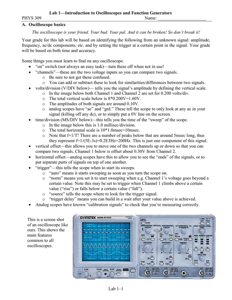
Lab 1—Introduction to Oscilloscopes and Function Generators PHYS 309 Name: A. Oscilloscope basics The oscilloscope is your friend. Your bud. Your pal. And it can be broken! So don’t break it! Your grade for this lab will be based on identifying the following from an unknown signal: amplitude, frequency, ac/dc components, etc. and by setting the trigger at a certain point in the signal. Your grade will be based on both time and accuracy. Some things you must learn to find on any oscilloscope. • “on” switch (not always an easy task)—turn these off when not in use! • “channels”—these are the two voltage inputs so you can compare two signals. o Be sure to not get these confused. o You can add or subtract these to look for similarities/differences between two signals. • volts/division (V/DIV below)— tells you the signal’s amplitude by defining the vertical scale. o In the image below both Channel 1 and Channel 2 are set for 0.200 volts/div. o The total vertical scale below is 8*0.200V=1.60V. o The amplitudes of both signals are around 0.10V. o analog scopes have “ac” and “grd.” These tell the scope to only look at any ac in your signal (killing off any dc), or to simply put a 0V line on the screen. • time/division (MS/DIV below)—this tells you the time of the “sweep” of the scope. o In the image below this is 1.0 millisec/division. o The total horizontal scale is 10*1.0msec=10msec. o Note that f=1/T! There are a number of peaks below that are around 5msec long, thus they represent f=1/(5E-3s)=0.2E3Hz=200Hz. This is just one component of this signal. • vertical offset—this allows you to move one of the two channels up or down so that you can compare two signals. Channel 1 below is offset about 0.30V from Channel 2. • horizontal offset—analog scopes have this to allow you to see the “ends” of the signals, or to put separate parts of signals on top of one another. • “trigger”—this tells the scope when to start its sweeps. o “auto” means it starts sweeping as soon as you turn the scope on. o “norm” means you set it to start sweeping when e.g. Channel 1’s voltage goes beyond a certain value. Note this may be set to trigger when Channel 1 climbs above a certain value (“rise”) or falls below a certain value (“fall”). o “source” tells the scope where to look for the trigger signal. o “trigger delay” means you can build in a wait after your value above is achieved. • Analog scopes have known “calibration signals” to check that you’re measuring correctly. This is a screen shot of an oscilloscope like ours. This shows the main features common to all oscilloscopes. Lab 1–1 Lab 1—Introduction to Oscilloscopes and Function Generators PHYS 309 Name: B. Function generator basics Function generators generate various waves, with the most useful of them (for our purposes) being sine waves. Function generators allow you to set the amplitude, frequency and shape (sine, triangular, square) of the wave. Sometimes they allow you to set the dc offset, which is simply a dc voltage added to the oscillating signal. • • You need to get used to the “multiplier” and “decade” buttons. This is simply the electronic version of scientific notation, e.g. 1.2 x 10⁴Hz. You should be able to quickly set any function generator to deliver e.g. a 200kHz signal, or a signal with a time period of 33µsec (which means do the math in your head quickly), or any other signal chosen. The first rule in all electronics is, Always know where your ground is. Do not connect the ground to your signal or you will dump your voltage straight to ground with no resistance. Using Ohm’s Law this means I=V/R=V/0=infinity=smoke=<sadface>. The second rule of electronics is, Do not let the smoke out of an electronic component. The smoke hidden within a circuit element is the life force of that element. It must always remain hidden. Once that smoke is let out, the element is dead. C. Assignment: oscilloscope/function generator test Sign up for one time to take the oscilloscope/function generator test. The allowable times will be posted on my door and will be before 5pm on Monday. I will have a function generator dialed up to a signal with an unknown frequency and Vpp. The oscilloscope that I use will be off, will have the dials scrambled, and the probe will be unplugged. You will have 210 seconds (3.5 minutes) to do the following with no help from me or anyone else. You may not use a calculator for anything. • • • • • • • [25 pts] Get the unknown signal on the screen, with a scale that’s easy to read. [25 pts] Get the unknown signal frequency-stabilized on the screen. [20 pts] Determine the Vpp with the correct units. [15 pts] Determine the time period T of the signal with the correct units. [15 pts] Determine the frequency f with the correct units. One point will be subtracted from your overall score for every three seconds beyond 210s that you require to complete this task. No one else may be in the lab while someone’s test is in progress. Lab 1–2

