- Series 4400 Float Operated Level Controls for lateral internal
advertisement

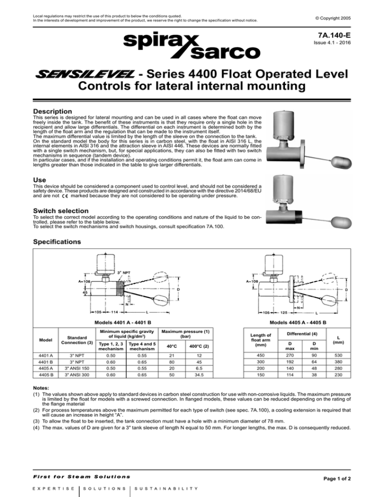
Local regulations may restrict the use of this product to below the conditions quoted. In the interests of development and improvement of the product, we reserve the right to change the specification without notice. © Copyright 2005 7A.140-E Issue 4.1 - 2016 - Series 4400 Float Operated Level Controls for lateral internal mounting Description This series is designed for lateral mounting and can be used in all cases where the float can move freely inside the tank. The benefit of these instruments is that they require only a single hole in the recipient and allow large differentials. The differential on each instrument is determined both by the length of the float arm and the regulation that can be made to the instrument itself. The maximum differential value is limited by the length of the sleeve on the connection to the tank. On the standard model the body for this series is in carbon steel, with the float in AISI 316 L, the internal elements in AISI 316 and the attraction sleeve in AISI 446. These devices are normally fitted with a single switch mechanism, but, for special applications, they can also be fitted with two switch mechanisms in sequence (tandem device). In particular cases, and if the installation and operating conditions permit it, the float arm can come in lengths greater than those indicated in the table to give larger differentials. Use This device should be considered a component used to control level, and should not be considered a safety device. These products are designed and constructed in accordance with the directive 2014/68/EU and are not marked because they are not considered to be operating under pressure. Switch selection To select the correct model according to the operating conditions and nature of the liquid to be controlled, please refer to the table below. To select the switch mechanisms and switch housings, consult specification 7A.100. Specifications Models 4401 A - 4401 B Model Standard Connection (3) Minimum specific gravity of liquid (kg/dm3) Models 4405 A - 4405 B Maximum pressure (1) (bar) Type 1, 2, 3 mechanism Type 4 and 5 mechanism 40°C 400°C (2) Length of float arm (mm) Differential (4) D max D min L (mm) 4401 A 3" NPT 0.50 0.55 21 12 450 270 90 530 4401 B 3" NPT 0.60 0.65 80 45 300 192 64 380 4405 A 3" ANSI 150 0.50 0.55 20 6.5 200 140 48 280 4405 B 3" ANSI 300 0.60 0.65 50 34.5 150 114 38 230 Notes: (1) The values shown above apply to standard devices in carbon steel construction for use with non-corrosive liquids. The maximum pressure is limited by the float for models with a screwed connection. In flanged models, these values can be reduced depending on the rating of the flange material (2) For process temperatures above the maximum permitted for each type of switch (see spec. 7A.100), a cooling extension is required that will cause an increase in height “A”. (3) To allow the float to be inserted, the tank connection must have a hole with a minimum diameter of 78 mm. (4) The max. values of D are given for a 3" tank sleeve of length N equal to 50 mm. For longer lengths, the max. D is consequently reduced. Page 1 of 2 Tandem device This special solution can only be supplied with type 1, 2 or 3 switch mechanisms. Given the presence of two mechanisms the minimum admissible specific gravity is greater than that shown on the table by about 0.05 kg/dm³. The settings for switching points and individual switch differentials are factory set on request. For the mercury switches, the differential is fixed, while for the micro-switches it can be adjusted slightly (see table). Differential “D” Mercury switches D min. = D max. (1) (mm) 40 50 70 100 Arm length (mm) 150 200 300 450 Micro-switches D min. (mm) 20 25 35 50 D max. (2) (mm) 40 50 70 100 Notes: (1) Maximum length of connection rod N = 100 mm (2) With a connection rod length N = 150 mm, max. D is reduced by 25%; with a length N = 200 mm, max, D = Min. D Normally this instrument is calibrated as in figure 1, but for special applications the switching heights can be changed with respect to the middle value of one or both switch mechanisms, while maintaining the differential between the individual mechanisms, or else increasing it, but still with respect to the maximum level heights H2 and minimum level heights L1 (see figure 2). Fig. 1 Fig. 2 Options and special features (2) • • • • • • Body in AISI 316 or other special corrosion-resistant materials Attraction sleeve with anti-corrosion coating Compliance with standard NACE MR 01 - 75 Special distances between switching levels Interface control setting Double stage device How to request or order Each instrument is identified by an alphanumeric code describing the construction specifications in part only. This code is formed of three components, each of which defines part of the instrument: the first identifies the sensing unit model (chamber and float), the second identifies the type and quantity of switch mechanisms, and the third identifies the type of switch housing. It is therefore necessary to specify the material used for the chamber and internal elements, the flange type (for flanged device), arm lenght, and any other special requests. Example: Mod. 4405 B - 110 - 4 - S Options (connections, interface, etc.) Flameproof switch housing (see specification 7A.100) 1 SPDT mercury switch mechanisms (see specification 7A.100) Sensing unit model 7A.140-E Issue 4.1 - 2016.07 Via per Cinisello, 18 - 20834 Nova Milanese (MB) Tel.: 0362 49 17.1 - Fax: 0362 49 17 307 Page 2 of 2

