DIFFRACTION AND PLANE BOUNDARIES
advertisement
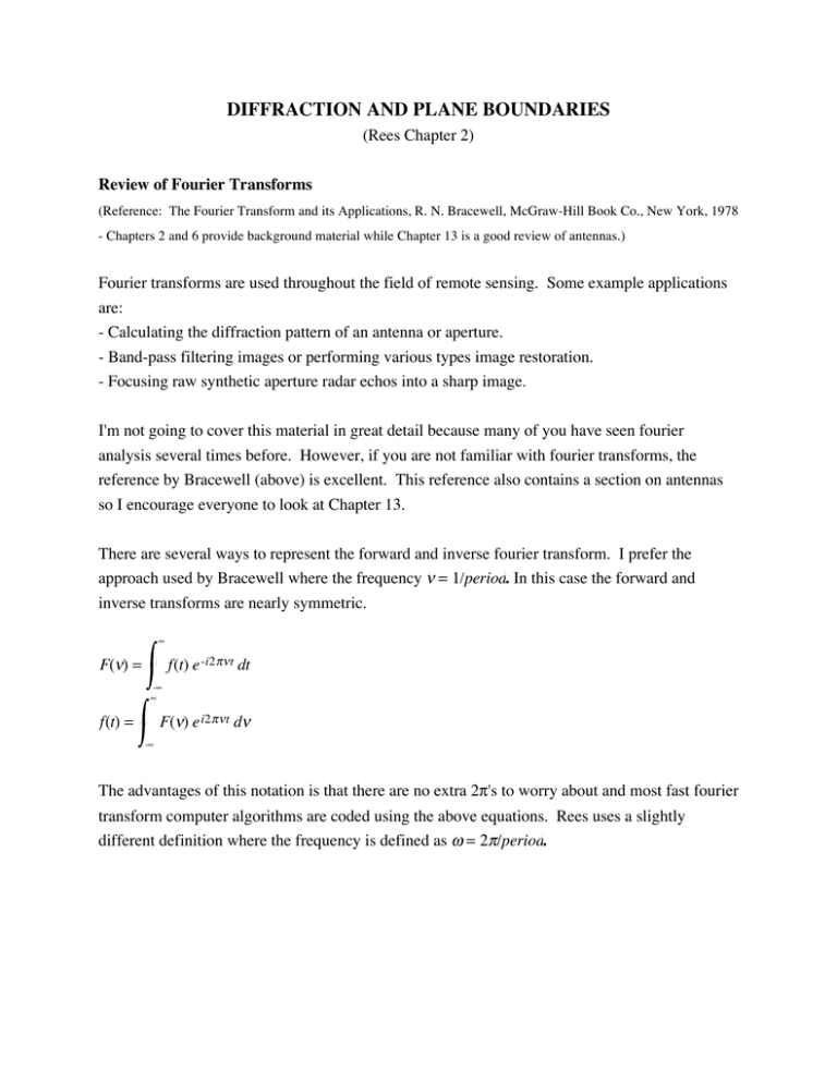
DIFFRACTION AND PLANE BOUNDARIES (Rees Chapter 2) Review of Fourier Transforms (Reference: The Fourier Transform and its Applications, R. N. Bracewell, McGraw-Hill Book Co., New York, 1978 - Chapters 2 and 6 provide background material while Chapter 13 is a good review of antennas.) Fourier transforms are used throughout the field of remote sensing. Some example applications are: - Calculating the diffraction pattern of an antenna or aperture. - Band-pass filtering images or performing various types image restoration. - Focusing raw synthetic aperture radar echos into a sharp image. I'm not going to cover this material in great detail because many of you have seen fourier analysis several times before. However, if you are not familiar with fourier transforms, the reference by Bracewell (above) is excellent. This reference also contains a section on antennas so I encourage everyone to look at Chapter 13. There are several ways to represent the forward and inverse fourier transform. I prefer the approach used by Bracewell where the frequency ν = 1/period. In this case the forward and inverse transforms are nearly symmetric. ∞ F(ν) = f(t) e -i2 πν t dt -∞ ∞ F(ν) e i2 πν t dν f(t) = -∞ The advantages of this notation is that there are no extra 2π's to worry about and most fast fourier transform computer algorithms are coded using the above equations. Rees uses a slightly different definition where the frequency is defined as ω = 2π/period. ∞ a(ω) = 1 2π f(t) e -iω t dt -∞ ∞ a(ω) e iω t dω f(t) = -∞ Example: f(t) = cos ωo t Using a waveform generator one could generate a function at a single frequency ωo. Suppose we recorded this waveform over a finite time interval T. What does the spectrum look like? If the recording were infinitely long, the spectrum would be a delta-function with peaks at a frequencies ±ωο. In the real world, one can only record a signal over a finite period of time called a window. Later we'll use the term aperture which is the spatial equivalent of a time window. For a finite time window of length T, the Fourier transform is a(ω) = 1 2π T 2 cosωo t e -iω t dt -T 2 Of course cosθ = e a(ω) = 1 1 2π 2 iθ + e -i θ so we can express this as the sum of two integrals. 2 T 2 e i ωo − -T 2 ωt dt + 1 2 T 2 e -i ωo + ωt dt -T 2 The first integral inside of the brackets is first integral = 1 2i ωo − ω e i ωo − ω T 2 - e -i ωo − ω T 2 sin ωo − ω T 2 = ωo − ω The second integral is similar and the overall result is 1 a (ω ) = πT T T ⎡ ⎢ sin (ω o − ω ) 2 sin (ω o + ω ) 2 + ⎢ T T ⎢ (ω o − ω ) ωo + ω ) ( ⎣ 2 2 ⎤ ⎥ 1 ⎡ T T⎤ sin c (ω o − ω ) + sin c (ω o + ω ) ⎥ ⎥= ⎢ 2 2⎦ ⎥ πT ⎣ ⎦ A crude graph of the function (below) relates the spectrum of the finite window to the spectrum of the infinite window. 1 − ωο ωο Δω The finite time window broadens the spectral pulse from a delta function to a sinc function. The 4π width of the spectral peak is Δω = . Increasing the recording time will decrease the width of T the spectral peak, or as we'll see next, increasing the diameter of the aperture of a telescope will improve its angular resolution. Diffraction Next consider the projection pattern of coherent radiation after it passes through an aperture. First we'll consider a 1-D aperture and then go on to a 2-D rectangular aperture and finally a circular aperture or dish antenna. Although we will develop the resolution characteristics of apertures as transmitters of radiation, the resolution characteristics are exactly the same when the aperture is used to receive radiation. Again these notes are straight out of Rees or Bracewell. y screen aperture P L/2 A θ O z -L/2 A O y sin θ We simulate coherent radiation by point sources of radiation distributed along the aperture between -L/2 and L/2. For simplicity we'll assume all the sources have the same amplitude, wavelength λ, and phase. Given these sources of radiation, what is the illumination pattern on the screen as a function of θ. We'll assume that the screen is far enough from the aperture so that rays AP and OP are parallel. Later we'll determine how far away the screen needs to be in order for this approximation to hold. Under these conditions, the ray AP is slightly shorter than the ray OP by an amount -y sinθ . This corresponds to a phase shift of -2π y sinθ . The amplitude of the illumination at point P is λ the integral over all of the sources along the aperture multiplied by their complex phase value P (θ ) = L /2 ∫ A ( y )e −iy 2π sin θ λ dy . − L /2 This is called the Fraunhofer diffraction integral. The illumination across the aperture is uniform 2π in both amplitude and phase so we set A(y) = 1. Now let s = sin θ so the integral becomes a λ fourier transform that is easy to integrate. L 2 P(s) = -L 2 -i sL i sL e -isy dy = e 2 - e 2 = 2s sin sL = L sinc sL -is 2 2 Replacing s with 2π sin θ we arrive at the final result. λ ⎛ π L sin θ ⎞ P (θ ) = L sin c ⎜ ⎝ λ ⎟⎠ The first zero crossing of the sinc function occurs when the argument is π so the angular resolution of our aperture is simply sinθ r = λ /L and for small angles, θ r ≅ λ /L . Note that one could modify the screen illumination by changing the strength of the illumination across the active part of the aperture. For example, a Gaussian aperture would produce a Gaussian illumination function on the screen. This would eliminate the sidelobes associated with the sinc function but it would also decrease the angular resolution. In addition one could vary the phase along the aperture to shift the point of maximum illumination away from θ = 0. Such a phased array aperture is used in some radar systems to continuously-illuminate a feature as the satellite passed over it. This is called spotlight mode SAR and it is a favorite technique for military reconnaissance. One can perform the same type of analysis with any 2-D aperture; many analytic examples are given in Figure 12.4 from Bracewell. Later we'll be using a rectangular aperture when we discuss synthetic aperture radars. A uniform circular aperture has an angular resolution given by sinθ r = 1.22 λ/L. Example of a Circular Aperture: The Geosat radar altimeter orbits the Earth at an altitude of 800 km and illuminates the ocean surface with a 1-m parabolic dish antenna operating at Ku band (13.5 GHz, λ = 0.022m). What is the diameter of the beam-limited footprint on the ocean surface? θr H Ds The diameter is simply Ds = 2 H sin θ r = 2.44 H λ or in this case 43 km. D Next lets consider an optical system with the same 1 m diameter aperture. λ = 5 x 10⁻⁷ m D=1m H = 800,000 m The diameter of the footprint Ds = 0.97 m. The Hubble space telescope reports and angular resolution of 0.1 arcsecond which corresponds to an effective aperture of 1.27 m. Thus a 1-m ground resolution is possible for optical systems. Fraunhofer Diffraction vs Fresnel Diffraction The assumption that we used in developing the Fraunhofer diffraction integral is that the rays AP and OP are parallel. Suppose we examine the case when θ = 0; the ray path AP is slightly longer than OP. This parallel-ray assumption breaks down when the phase of ray path AP is more than π/2 radians longer than OP which corresponds to a distance of λ/4. Lets determine the conditions when this happens. L 2 + z 2 1/2 4 A L/2 P O z L 2 + z 2 1/2 - z < λ 4 4 L 2z 2 +1 1/2 - 1< λ 4z Now assume L < z so we can expand the term in bracket in a binomial series. 2 1 + L -1< λ 4z 8z 2 or 2 zf > L - Fresnel distance 2λ So when z < zf we are in the near field and we need to use a more rigorous diffraction theory. However when z >> zf we are safe to use the parallel-ray approximation and the Fraunhofer diffraction integral is appropriate. Examples: Geosat; L = 1m, λ = 0.022m zf = 23m At an orbital altitude of 800 km the parallel-ray approximation is valid. Optical telescope; L = 1 m, λ = 5 x 10⁻⁷ m zf = 4000 km. So we see that an optical system with an orbital altitude of 800 km will require near-field optics. What about a synthetic aperture radar such as ERS with a 1000 m long synthetic aperture. ERS SAR; L = 1000 m, λ = 0.058m zf = 8000 km. Thus near-field optics are also required to achieve full SAR resolution for ERS. This is done in the SAR processor by performing a step called range migration and it is a large factor in making SAR processing so CPU-intensive. Plane Boundaries Snell's Law θ1 θ1 θ2 n1 n2 n1 sinθ 1 = n2 sinθ 2 Rees provides all the expressions for the reflection and transmission coefficients r and t on page 34 so I won't repeat them here. However, there is a special interesting case if medium 1 is a vacuum and medium 2 is lossless with index of refraction n. r⊥ = r|| = n 2 - sin2 θ 1/2 n 2 - sin2 θ 1/2 - cos θ + cos θ n 2 cosθ − n 2 - sin2 θ 1/2 n 2 cosθ + n 2 - sin2 θ 1/2 The vertically polarized radiation has a zero reflection coefficient r|| = 0 when n 2 cosθ = n 2 - sin2 θ 1/2 n 4 cos2 θ = n 2 - sin2 θ tan θ B = n (Note that the || component is parallel to the plane formed by the incident and reflected ray; it is not parallel to the reflecting surface. Also note that it is difficult to derive the third equation (above) from the second although it is easy to show that the third equation is true!) The angle θB is called Brewster's angle (See Halliday and Resnick, Fig. 46-8 and 46-9). Sea water Sea water visible light n = 1.34 θB = 53.26˚ 1 GHz n = 9 θB = 83.65˚ Experiment: Hold your polarized sun glasses between your eyes and the ocean surface and observe the intensity of the transmitted light as the glasses are rotated.
