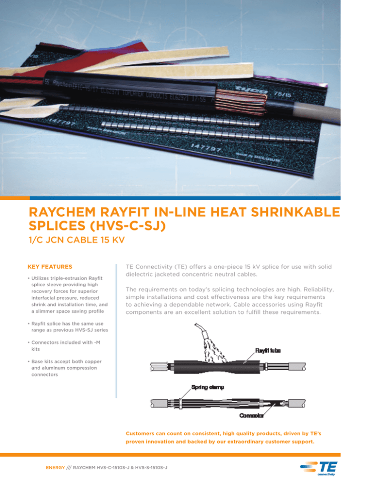
RAYCHEM RAYFIT IN-LINE HEAT SHRINKABLE
SPLICES (HVS-C-SJ)
1/C JCN CABLE 15 KV
KEY FEATURES
•U
tilizes triple-extrusion Rayfit
splice sleeve providing high
recovery forces for superior
interfacial pressure, reduced
shrink and installation time, and
a slimmer space saving profile
TE Connectivity (TE) offers a one-piece 15 kV splice for use with solid
dielectric jacketed concentric neutral cables.
The requirements on today’s splicing technologies are high. Reliability,
simple installations and cost effectiveness are the key requirements
to achieving a dependable network. Cable accessories using Rayfit
components are an excellent solution to fulfill these requirements.
•R
ayfit splice has the same use
range as previous HVS-SJ series
• Connectors
included with -M
kits
•B
ase kits accept both copper
and aluminum compression
connectors
Customers can count on consistent, high quality products, driven by TE’s
proven innovation and backed by our extraordinary customer support.
ENERGY /// RAYCHEM HVS-C-1510S-J & HVS-S-1510S-J
HVS Product Specifications
ADDITIONAL FEATURES
•H
VS-C-151xS-J–M1 and M2 kits include a range taking
copper ShearBolt connector for use with copper
conductor
•H
VS-S-151xS-J-M (4-9) and M9 kits include a range
taking aluminum ShearBolt connector for use with
aluminum or copper conductor. HVS S-152x-M (4-9)
kits are supplied with stress control shim tubes to
increase the insulation diameter
TESTING
•A
ll HVS-C-1510S-J and HVS-S-1510S-J splices
have been qualified to IEEE-404-2006 at 105˚C.
(140˚C emergency operation) with the outer
wraparound jacket removed for underwater
load cycling
SELECTION INFORMATION: DIMENSIONS IN INCHES (MILLIMETERS)
Catalog
Number
Conductor Size
(AWG/kcmil)
Insulation Diameter
(Min-Max)
Jacket O.D.
(Max)
Maximum Connector Dimensions
Length
O.D.
Kit Installed
Length
Required
Installation Space
A
B
C
L
M
HVS-C-1510S-J Without Connector
HVS-C-1511S-J
#2 – 2/0
0.65 - 0.95 (17 - 24)
1.20 (30)
4.00 (100)
0.80 (20)
28.00 (700)
28.00 (700)
HVS-C-1512S-J
3/0 - 400
0.85 - 1.30 (23 - 33)
1.65 (42)
5.00 (125)
1.20 (30)
28.00 (700)
28.00 (700)
HVS-C-1513S-J
500 - 750
1.10 - 1.55 (28 - 47)
1.90 (48)
6.00 (150)
1.45 (44)
35.00 (870)
35.00 (870)
HVS-C-1514S-J
750 - 1000
1.30 - 1.90 (33 - 48)
2.30 (58)
8.00 (200)
1.85 (47)
35.00 (870)
35.00 (870)
Catalog
Number
Conductor Size
(AWG/kcmil)
Insulation Diameter
(Min-Max)
Jacket O.D.
(Max)
Maximum Connector Dimensions
Length
O.D.
Kit Installed
Length
Required
Installation Space
A
B
C
L
M
HVS-C-1510S-J with Copper Mechanical ShearBolt Connector
HVS-C-1512S-J-M1
3/0 - 400
0.85 - 1.30 (23 - 33)
1.20 (30)
4.0 (100)
1.20 (30)
28.00 (700)
28.00 (700)
HVS-C-1513S-J-M2
500 - 750
1.10 - 1.55 (28 - 47)
1.45 (47)
5.0 (125)
1.45 (37)
35.00 (870)
35.00 (870)
Insulation Diameter
(Min-Max)
Jacket O.D.
(Max)
Maximum Connector Dimensions
Length
O.D.
Kit Installed
Length
Required
Installation Space
A
B
C
L
M
M1 = CSBS-20C-500C-SOS
M2 = CSBS-300C-750C-SOS
Catalog
Number
Conductor Size
(AWG/kcmil)
HVS-S-1510S-J-with Aluminum Mechanical ShearBolt Connector
HVS-S-1512S-J-M4
#2 – 2/0
0.65 - 0.95 (17 - 24)
1.20 (30)
2.50 (65)
.095 (24)
28.00 (700)
28.00 (700)
HVS-S-1512S-J-M5
2/0 - 350
0.79 - 1.19 (20 - 30)
1.65 (42)
4.00 (100)
1.25 (30)
28.00 (700)
28.00 (700)
HVS-S-1513S-J-M6
350 - 500
1.04 - 1.33 (26 - 34)
1.80 (45)
5.00 (125)
1.30 (34)
35.00 (870)
35.00 (870)
HVS-S-1514S-J-M8
500 - 750
1.16 - 1.55 (29 - 39)
1.90 (48)
6.00 (150)
1.55 (40)
35.00 (870)
35.00 (870)
HVS-S-1514S-J-M9
750 - 1000
1.35 - 1.70 (34 - 43)
2.30 (58)
8.00 (200)
1.75 (43)
35.00 (870)
35.00 (870)
M4 = ASBS-2-3/0
M5 = ASBS-2-350
M6 = ASBS-3/0-500
M8 = ASBS-500-750
M9 = ASBS-600-1000
Ordering Information
1. Select the appropriate catalog number. All selections are based
on the typical dimensions for both 100 and 133% insulated cables,
nominal insulation thickness 0.175-0.220”.
4. If external grounding, contact TE Connectivity for modified
installation instructions.
2. Use the insulation OD, and jacket OD range as the final ordering
criteria.
6. Related Test Report: EDR-5440 and EDR-5444, IEEE 404-2006
and IEEE 48 draft 2006 for 105˚C of Splice and Terminations.
3. Kits can be installed with either aluminum or copper compression
connectors (connectors not included with kit).
7. For AL Mechanical ShearBolt connector information request
datasheet 9-1773440-4 and for CU request 165972.
5. Standard package: 1 kit/box
te.com/energy
©2009, 2010, 2012, 2015 TE Connectivity Ltd. family of companies. All Rights Reserved. 4-1773457-0 E385
Raychem, TE, TE Connectivity and TE connectivity (logo) are trademarks. Other logos, product and/or company names might be trademarks of their
respective owners. While TE has made every reasonable effort to ensure the accuracy of the information in this brochure, TE does not guarantee
that it is error-free, nor does TE make any other representation, warranty or guarantee that the information is accurate, correct, reliable or current.
TE reserves the right to make any adjustments to the information contained herein at any time without notice. TE expressly disclaims all implied
warranties regarding the information contained herein, including, but not limited to, any implied warranties of merchantability or fitness for a
particular purpose. The dimensions in this catalog are for reference purposes only and are subject to change without notice. Specifications are
subject to change without notice. Consult TE for the latest dimensions and design specifications.
ENERGY /// RAYCHEM HVS-C-1510S-J & HVS-S-1510S-J
FOR MORE INFORMATION:
TE Technical Support Centers
USA:
+1 (800) 327-6996
Canada:
+1 (905) 475-6222
Mexico
+52 (0) 55-1106-0800
Latin/S. America: +54 (0) 11-4733-2200
UK: +44 (0) 800-267666
France: +33 (0) 1-3420-8686
Netherlands:
+31 (0) 73-6246-999
China: +86 (0) 400-820-6015
RAYCHEM IN-LINE HEAT SHRINKABLE SPLICES
(RAYFIT HVS-C)
1/C SHIELDED LONGITUDINAL CORRUGATED & FS CABLES 15 kV
KEY FEATURES
•U
tilizes triple-extrusion Rayfit
splice sleeve providing reduced
shrink and installation time, and
a slimmer space saving profile
•S
ame use range as prior HVS1530-LC splice series
TE Connectivity (TE) Rayfit one-piece 15 kV splice is for use with solid
dielectric cables: longitudinal corrugated and flat strap neutral cables.
The requirements on today’s splicing technologies are high. Reliability,
simple installations and cost effectiveness are the key requirements
to achieving a dependable network. Cable accessories using Rayfit
components are an excellent solution to fulfill these requirements.
• Connectors included in -M kits
•A
ll kits contain two #4 AWG
solder blocked braids for
external grounding if required,
and four heavy duty constant
tension clamps
Customers can count on consistent, high quality products, driven by TE’s
proven innovation and backed by our extraordinary customer support.
ENERGY /// RAYCHEM HVS-C-1510S-J & HVS-S-1510S-J
Rayfit Product Specifications
ADDITIONAL FEATURES
•H
VS-C-153xS–M1 and M2 kits include a range
taking copper ShearBolt connector for use with
copper conductor
TESTING
•A
ll HVS-C-1530S and HVS-S-1530S splices have
been qualified to IEEE-404-2006 at 105˚C.
(140˚C emergency operation) with the outer
wraparound jacket removed for underwater
load cycling
•H
VS-S-153xS -M (4-9) kits include a range taking
aluminum ShearBolt connector for use with
aluminum or copper conductor. HVS-S-153xS-M
(4-9) kits are supplied with stress control shim
tubes to increase the insulation diameter
SELECTION INFORMATION: DIMENSIONS IN INCHES (MILLIMETERS)
Catalog
Number
Conductor Size
(AWG/kcmil)
Insulation Diameter
(Min-Max)
Jacket O.D.
(Max)
Maximum Connector Dimensions
Length
O.D.
Kit Installed
Length
Required
Installation Space
A
B
C
L
M
HVS-C-1530S Without Connector
HVS-C-1531S
#2 – 2/0
0.65 - 0.95 (17 - 24)
1.20 (30)
4.00 (100)
0.80 (20)
28.00 (700)
28.00 (700)
HVS-C-1532S
3/0 - 400
0.85 - 1.30 (23 - 33)
1.65 (42)
5.00 (125)
1.20 (30)
28.00 (700)
28.00 (700)
HVS-C-1533S
500 - 750
1.10 - 1.55 (28 - 47)
1.90 (48)
6.00 (150)
1.45 (44)
35.00 (870)
35.00 (870)
HVS-C-1534S
750 - 1000
1.30 - 1.90 (33 - 48)
2.30 (58)
8.00 (200)
1.85 (47)
35.00 (870)
35.00 (870)
Catalog
Number
Conductor Size
(AWG/kcmil)
Insulation Diameter
(Min-Max)
Jacket O.D.
(Max)
Maximum Connector Dimensions
Length
O.D.
Kit Installed
Length
Required
Installation Space
A
B
C
L
M
HVS-C-1530S with Copper Mechanical ShearBolt Connector
HVS-C-1532S-M1
3/0 - 400
0.85 - 1.30 (23 - 33)
1.20 (30)
4.0 (100)
1.20 (30)
28.00 (700)
28.00 (700)
HVS-C-1533S-M2
500 - 750
1.10 - 1.55 (28 - 47)
1.45 (47)
5.0 (125)
1.45 (37)
35.00 (870)
35.00 (870)
Insulation Diameter
(Min-Max)
Jacket O.D.
(Max)
Maximum Connector Dimensions
Length
O.D.
Kit Installed
Length
Required
Installation Space
A
B
C
L
M
M1 = CSBS-20C-500C-SOS
M2 = CSBS-300C-750C-SOS
Catalog
Number
Conductor Size
(AWG/kcmil)
HVS-S-1530S with Aluminum Mechanical ShearBolt Connector
HVS-S-1532S-M4
#2 – 2/0
0.65 - 0.95 (17 - 24)
1.20 (30)
2.50 (65)
.095 (24)
28.00 (700)
28.00 (700)
HVS-S-1532S-M5
2/0 - 350
0.79 - 1.19 (20 - 30)
1.65 (42)
4.00 (100)
1.25 (30)
28.00 (700)
28.00 (700)
HVS-S-1533S-M6
350 - 500
1.04 - 1.33 (26 - 34)
1.80 (45)
5.00 (125)
1.30 (34)
35.00 (870)
35.00 (870)
HVS-S-1534S-M8
500 - 750
1.16 - 1.55 (29 - 39)
1.90 (48)
6.00 (150)
1.55 (40)
35.00 (870)
35.00 (870)
HVS-S-1534S-M9
750 - 1000
1.35 - 1.70 (34 - 43)
2.30 (58)
8.00 (200)
1.75 (43)
35.00 (870)
35.00 (870)
M4 = ASBS-2-3/0
M5 = ASBS-2-350
M6 = ASBS-3/0-500
M8 = ASBS-500-750
M9 = ASBS-600-1000
Ordering Information
1. Select the appropriate catalog number. All selections are based
on the typical dimensions for both 100 and 133% insulated cables,
nominal insulation thickness 0.175-0.220”.
4. If external grounding, contact Tyco Electronics for modified
installation instructions.
2. Use the insulation OD, and jacket OD range as the final ordering
criteria.
6. Related Test Report: EDR-5440 and EDR-5444, IEEE 404-2006
and IEEE 48 draft 2006 for 105˚C of Splice and Terminations.
3. Kits can be installed with either aluminum or copper compression
connectors (connectors not included with kit).
7. For AL Mechanical ShearBolt connector information request
datasheet 9-1773440-4 and for CU request 165972.
5. Standard package: 1 kit/box
te.com/energy
©2006-2008, 2015 TE Connectivity Ltd. family of companies. All Rights Reserved. 2-1773453-8 E322 6/15
Raychem, TE, TE Connectivity and TE connectivity (logo) are trademarks. Other logos, product and/or company names might be trademarks of their
respective owners. While TE has made every reasonable effort to ensure the accuracy of the information in this brochure, TE does not guarantee
that it is error-free, nor does TE make any other representation, warranty or guarantee that the information is accurate, correct, reliable or current.
TE reserves the right to make any adjustments to the information contained herein at any time without notice. TE expressly disclaims all implied
warranties regarding the information contained herein, including, but not limited to, any implied warranties of merchantability or fitness for a
particular purpose. The dimensions in this catalog are for reference purposes only and are subject to change without notice. Specifications are
subject to change without notice. Consult TE for the latest dimensions and design specifications.
ENERGY /// RAYCHEM HVS-C-1510S-J & HVS-S-1510S-J
FOR MORE INFORMATION:
TE Technical Support Centers
USA:
+1 (800) 327-6996
Canada:
+1 (905) 475-6222
Mexico
+52 (0) 55-1106-0800
Latin/S. America: +54 (0) 11-4733-2200
UK: +44 (0) 800-267666
France: +33 (0) 1-3420-8686
Netherlands:
+31 (0) 73-6246-999
China: +86 (0) 400-820-6015
RAYCHEM IN-LINE HEAT SHRINK REPAIR SPLICES
(RAYFIT) FOR 15 KV AND 25 KV
KEY FEATURES
• One kit replaces two
conventional splices for
most repairs
• Splice includes extra
long tin plated aluminum
shearbolt connector
TE Connectivity’s new 15 kV and 25 kV repair splice, for use with either
copper tape shield or jacketed concentric neutral cables.
This series of splices utilizes the new triple-extrusion Rayfit splice
sleeve which provides high recovery forces resulting in superior
interfacial pressure, reduced shrink and installation time, and a slimmer
space-saving profile.
• Each kit contains all of
the components required
for the complete joint
assembly
• All HVS joints have been
qualified to the latest
version of IEEE-404
Customers can count on consistent, high quality products, driven by TE’s
proven innovation and backed by our extraordinary customer support.
ENERGY /// RAYCHEM RAYFIT REPAIR SPLICES
Rayfit Product Specifications
For Jacketed Concentric Neutral and Unjacketed Concentric Neutral Cables (-10 Series)
SELECTION INFORMATION: DIMENSIONS IN INCHES (MILLIMETERS)
Catalog
Number
Conductor Size
(AWG/kcmil)
Jacket O.D.
(Max)
Insulation Diameter
(Min-Max)
Connector Dimensions
Length
Diameter
Kit Installed
Length
Required
Installation Space
15 kV HVS-C-1510S-RJ-MX
HVS-C-1512S-RJ-M4
#2 – 2/0
1.20 (30)
.65 - .95 (17 - 24)
17.3 (440)
0.95 (24)
48.0
72.0
HVS-C-1512S-RJ-M5
2/0 - 350
1.65 (42)
.79 - 1.19 (20 - 30)
17.3 (440)
1.29 (33)
48.0
73.0
HVS-C-1513S-RJ-M7
350 - 500
1.80 (45)
1.04 - 1.33 (26 - 34)
17.3 (440)
1.45 (37)
48.0
74.0
HVS-C-1514S-RJ-M8
500 - 750
1.90 (48)
1.16 - 1.55 (29 - 39)
17.3 (440)
1.66 (42)
48.0
76.0
HVS-C-1514S-RJ-M9
750 - 1000
2.30 (58)
1.35 - 1.70 (34 - 43)
17.3 (440)
1.81 (46)
48.0
76.0
M4 = BSM-25/95-U-L440
Catalog
Number
Conductor Size
(AWG/kcmil)
M5 = BSM-95/240-U-L440
M7 = BSMU-120/300-L440
M8 = BSM-185/400-U-L440
M9 = BSMU-500-L440
Jacket O.D.
(Max)
Insulation Diameter
(Min-Max)
Connector Dimensions
Length
Diameter
Kit Installed
Length
Required
Installation Space
25 kV HVS-C-1510S-RJ-MX
HVS-C-2511S-RJ-M4
#2 – 3/0
1.65 (42)
.75 - 1.10 (19 - 28)
17.3 (440)
0.95 (24)
48.0
72.0
HVS-C-2512S-RJ-M5
4/0 - 350
2.15 (55)
1.03 - 1.50 (26 - 38)
17.3 (440)
1.29 (33)
48.0
73.0
HVS-C-2513S-RJ-M8
500 - 750
2.36 (60)
1.30 - 1.70 (34 - 43)
17.3 (440)
1.66 (42)
48.0
76.0
HVS-C-2514S-RJ-M9
1000
2.60 (65)
1.70 - 1.90 (43 - 49)
17.3 (440)
1.81 (46)
48.0
76.0
HVS-C-1514S-RJ-M9
750 - 1000
2.30 (58)
1.35 - 1.70 (34 - 43)
17.3 (440)
1.81 (46)
48.0
76.0
M4 = BSM-25/95-U-L440
M5 = BSM-95/240-U-L440
M8 = BSM-185/400-U-L440
M9 = BSMU-500-L440
For Copper Tape Shield, Wire Shield, UniShield and Lead Sheath Cables (-20 Series)
SELECTION INFORMATION: DIMENSIONS IN INCHES (MILLIMETERS)
Catalog
Number
Conductor Size
(AWG/kcmil)
Jacket O.D.
(Max)
Insulation Diameter
(Min-Max)
Connector Dimensions
Length
Diameter
Kit Installed
Length
Required
Installation Space
15 kV HVS-C-1520S-RJ-MX
HVS-C-1522S-RJ-M4
#2 – 2/0
1.20 (30)
.65 - .95 (17 - 24)
17.3 (440)
0.95 (24)
40.0
69.0
HVS-C-1522S-RJ-M5
2/0 - 350
1.65 (42)
.79 - 1.19 (20 - 30)
17.3 (440)
1.29 (33)
40.0
69.0
HVS-C-1523S-RJ-M7
350 - 500
1.80 (45)
1.04 - 1.33 (26 - 34)
17.3 (440)
1.45 (37)
44.0
71.0
HVS-C-1524S-RJ-M8
500 - 750
1.90 (48)
1.16 - 1.55 (29 - 39)
17.3 (440)
1.66 (42)
44.0
71.0
HVS-C-1524S-RJ-M9
750 - 1000
2.30 (58)
1.35 - 1.70 (34 - 43)
17.3 (440)
1.81 (46)
44.0
71.0
M4 = BSM-25/95-U-L440
Catalog
Number
Conductor Size
(AWG/kcmil)
M5 = BSM-95/240-U-L440
M7 = BSMU-120/300-L440
M8 = BSM-185/400-U-L440
M9 = BSMU-500-L440
Jacket O.D.
(Max)
Insulation Diameter
(Min-Max)
Connector Dimensions
Length
Diameter
Kit Installed
Length
Required
Installation Space
25 kV HVS-C-1520S-RJ-MX
HVS-C-2521S-RJ-M4
#2 – 3/0
1.65 (42)
.75 - 1.10 (19 - 28)
17.3 (440)
0.95 (24)
48.0
72.0
HVS-C-2522S-RJ-M5
4/0 - 350
2.15 (55)
1.03 - 1.50 (26 - 38)
17.3 (440)
1.29 (33)
48.0
73.0
HVS-C-2523S-RJ-M8
500 - 750
2.36 (60)
1.30 - 1.70 (34 - 43)
17.3 (440)
1.66 (42)
48.0
76.0
HVS-C-2524S-RJ-M9
1000
2.60 (65)
1.70 - 1.90 (43 - 49)
17.3 (440)
1.81 (46)
48.0
76.0
HVS-C-1514S-RJ-M9
750 - 1000
2.30 (58)
1.35 - 1.70 (34 - 43)
17.3 (440)
1.81 (46)
48.0
76.0
M4 = BSM-25/95-U-L440
M5 = BSM-95/240-U-L440
M8 = BSM-185/400-U-L440
M9 = BSMU-500-L440
Ordering Information
1. Select the appropriate catalog number. All selections are based
on the typical dimensions for both 100 and 133% insulated cables,
nominal insulation thickness 0.175-0.220”.
3. Standard package: 1 kit/box
2. Use the insulation OD, and jacket OD range as the final ordering
criteria.
5. For AL Mechanical ShearBolt connector information request
datasheet.
4. Related Test Report: EDR-5440, EDR-5444, EDR-5473, and
IEEE 404 for 105˚C of Splice and Terminations.
te.com/energy
©2006-2008, 2015 TE Connectivity Ltd. family of companies. All Rights Reserved. 2-1773453-7 E321 6/15
Raychem, TE, TE Connectivity and TE connectivity (logo) are trademarks. Other logos, product and/or company names might be trademarks of their
respective owners. While TE has made every reasonable effort to ensure the accuracy of the information in this brochure, TE does not guarantee
that it is error-free, nor does TE make any other representation, warranty or guarantee that the information is accurate, correct, reliable or current.
TE reserves the right to make any adjustments to the information contained herein at any time without notice. TE expressly disclaims all implied
warranties regarding the information contained herein, including, but not limited to, any implied warranties of merchantability or fitness for a
particular purpose. The dimensions in this catalog are for reference purposes only and are subject to change without notice. Specifications are
subject to change without notice. Consult TE for the latest dimensions and design specifications.
ENERGY /// RAYCHEM RAYFIT REPAIR SPLICES
FOR MORE INFORMATION:
TE Technical Support Centers
USA:
+1 (800) 327-6996
Canada:
+1 (905) 475-6222
Mexico
+52 (0) 55-1106-0800
Latin/S. America: +54 (0) 11-4733-2200
UK: +44 (0) 800-267666
France: +33 (0) 1-3420-8686
Netherlands:
+31 (0) 73-6246-999
China: +86 (0) 400-820-6015
RAYCHEM MEDIUM VOLTAGE TERMINATION
(HVT)
5 KV - 35 KV
KEY FEATURES
•B
road range of standard
indoor and outdoor kits
for all plastic cable types,
including armored cable
•E
asy installation with a
single technique which
eliminates retraining-even
on armored cable
• HVT termination system
may be installed upright
or inverted and can bend
to the same bending
radius as the cable
TE Connectivity’s (TE) Raychem HVT medium voltage termination system
features a non-tracking, insulating surface that can withstand long-term
electrical stress and surface pollution. The need for proven stress control
is even more important at higher voltages. The materials used in TE’s HVT
terminations are suitable for severely polluted areas and for all installation
conditions, including top feed installation.
Reliable, field proven performance
Independent testing and field experience have repeatedly proven the
long-term stability, durability and reliability of the HVT system, even in highly
polluted environments. The non-tracking, insulating outer jacket can withstand
the rigors of long-term electrical stress and surface pollution without loss of
performance. TE’s non-tracking material offers the additional benefit of being
maintenance free, with no need for periodic cleaning. Extensive load cycle
testing verifies the long-term thermomechanical compatibility between the
termination system and the cable.
Testing
TE’s medium-voltage terminations are fully qualified per IEEE-48 as Class I
terminations to provide a long, trouble-free service life.
Ease of installation
The HVT termination kits can be installed on all cable types without special
adapters or accessories.
ENERGY /// HVT MEDIUM VOLTAGE TERMINATION
HVT Product Specifications
PRODUCT SELECTION INFORMATION: DIMENSIONS IN INCHES (MILLIMETERS)
Indoor
Outdoor Kit
5/8 kV
Conductor Size (Min. – Max.)
5 kV (0.90")
8 kV (0.115")
Insulation Diameter (Min. – Max.)
Jacket O.D. (Max)
HVT-80-G
HVT-80-SG
#4 AWG – #1* AWG
#6 AWG – #2 AWG
0.35 – 0.60 (9 – 15)
0.95 (24)
HVT-81-G
HVT-81-SG
1/0 AWG – 250* kcmil
#1 AWG – 4/0 AWG
0.60 – 0.95 (15 – 24)
1.20 (30)
HVT-82-G
HVT-82-SG
300 kcmil – 500* kcmil
250 kcmil – 500 kcmil
0.80 – 1.25 (20 – 32)
1.50 (38)
HVT-83-G
HVT-83-SG
600 kcmil – 1750* kcmil
600 kcmil – 1750 kcmil
1.10 – 1.75 (28 – 44)
2.10 (53)
HVT-84-G
HVT-84-SG
1500 kcmil – 2500* kcmil
2000 kcmil – 2500 kcmil
1.60 – 2.45 (41 – 62)
2.75 (70)
Insulation Diameter (Min. – Max.)
Jacket O.D. (Max)
Installed length: 10.5" (267mm)
Indoor
Outdoor Kit
15 kV
Conductor Size (Min. – Max.)
15 kV (.175 - .220")
HVT-151-G
HVT-151-SG
#4 AWG – 1/0 AWG
0.60–0.95 (15 – 24)
1.20 (30)
HVT-152-G
HVT-152-SG
2/0 AWG – 350 kcmil
0.80 – 1.25 (20 – 32)
1.50 (38)
HVT-153-G
HVT-153-SG
400 kcmil – 1000 kcmil
1.10 – 1.65 (28 – 42)
2.10 (53)
HVT-154-G
HVT-154-SG
1250 kcmil – 2500 kcmil
1.60 – 2.45 (41 – 62)
2.75 (70)
Conductor Size (Min. – Max.)
Insulation Diameter (Min. – Max.)
Jacket O.D. (Max)
Installed Length 15.0" (381 mm)
Indoor
Outdoor Kit
25 kV
25 kV (0.260")
HVT-252-G
HVT-252-SG
#2 AWG – 250 kcmil
0.80 – 1.25 (20 – 32)
1.50 (38)
HVT-253-G
HVT-253-SG
300 kcmil – 750 kcmil
1.10 – 1.70 (28 – 43)
2.10 (53)
HVT-254-G
HVT-254-SG
1000 kcmil – 1750 kcmil
1.60 – 2.45 (41 – 62)
2.75 (70)
HVT-255-G
HVT-255-SG
2000 kcmil – 2500 kcmil
2.05 – 3.00 (52 – 76)
3.45 (88)
Conductor Size (Min. – Max.)
Insulation Diameter (Min. – Max.)
Jacket O.D. (Max)
Installed Length 28.0" (711 mm)
Indoor
Outdoor Kit
35 kV
35 kV (0.345")
HVT-352-G
HVT-352-SG
#1 AWG – 1/0 AWG
0.80 – 1.25 (20 – 32)
1.50 (38)
HVT-353-G
HVT-353-SG
2/0 AWG – 500 kcmil
1.10 – 1.85 (28 – 47)
2.10 (53)
HVT-354-G
HVT-354-SG
750 kcmil – 1750 kcmil
1.60 – 2.45 (41 – 62)
2.75 (70)
HVT-355-G
HVT-355-SG
2000 kcmil – 2500 kcmil
2.05 – 3.00 (52 – 76)
3.45 (88)
Installed Length 33.0" (838 mm)
TESTING CHART:
Product and Voltage Class* Test Description
HVT-80 Series (5 - 8 kV)
HVT-150 Series (15 kV)
HVT-250 Series ( 25 kV)**
HVT-350 Series ( 35 kV)
AC Withstand, 1 minute, (kV)
35
50
65
90
DC Withstand, 15 minutes (kV)
65
75
105
140
Partial Discharge (min. kV) for 3 pc or less
9
15.6
25.8
36
Impulse withstand 1.2 X 50 us, crest kV (outdoor)***
95
110
150
200
Impulse withstand 1.2 X 50 us, crest kV (indoor)***
80
95
125
150
Continuous current rating
Equal to cable ampacity
Equal to cable ampacity
Equal to cable ampacity
Equal to cable ampacity
Wet withstand, 10 seconds, kV rms
30
45
60
80
Dry withstand, 6 hours, kV rms
25
35
55
75
Note: For PILC terminations, please refer to page 165 of Energy Ready Reference Guide 2012.
*
URD and LC kits are rated for 15 – 35 kV only; HVT-M kits for 5/8 – 25 kV only.
**
HVT-250 meets requirements of 25/28 kV systems.
***
Outdoor kits (-SJ, -SG, or -SLC designation) were tested with skirts (rain sheds).
Indoor kits (-J, -G, -LC designation) do not contain skirts.
FOR MORE INFORMATION:
TE Technical Support Centers
USA:
+1 (800) 327-6996
Canada:
+1 (905) 475-6222
©2005, 2007, 2009-2013, 2015 TE Connectivity Ltd. family of companies. All Rights Reserved. 1308239 E128 6/15
Mexico:
+52 (0) 55-1106-0800
Raychem, TE, TE Connectivity and TE connectivity (logo) are trademarks. Other logos, product and/or company names might
be trademarks of their respective owners. While TE has made every reasonable effort to ensure the accuracy of the information
in this brochure, TE does not guarantee that it is error-free, nor does TE make any other representation, warranty or guarantee
that the information is accurate, correct, reliable or current. TE reserves the right to make any adjustments to the information
contained herein at any time without notice. TE expressly disclaims all implied warranties regarding the information contained
herein, including, but not limited to, any implied warranties of merchantability or fitness for a particular purpose. The dimensions
in this catalog are for reference purposes only and are subject to change without notice. Specifications are subject to change
without notice. Consult TE for the latest dimensions and design specifications.
Latin/S. America: +54 (0) 11-4733-2200
te.com/energy
ENERGY /// HVT MEDIUM VOLTAGE TERMINATION
UK: +44 (0) 800-267666
France: +33 (0) 1-3420-8686
Netherlands:
+31 (0) 73-6246-999
China: +86 (0) 400-820-6015

