Solutions - Problem Set #11 – Chapter 30
advertisement
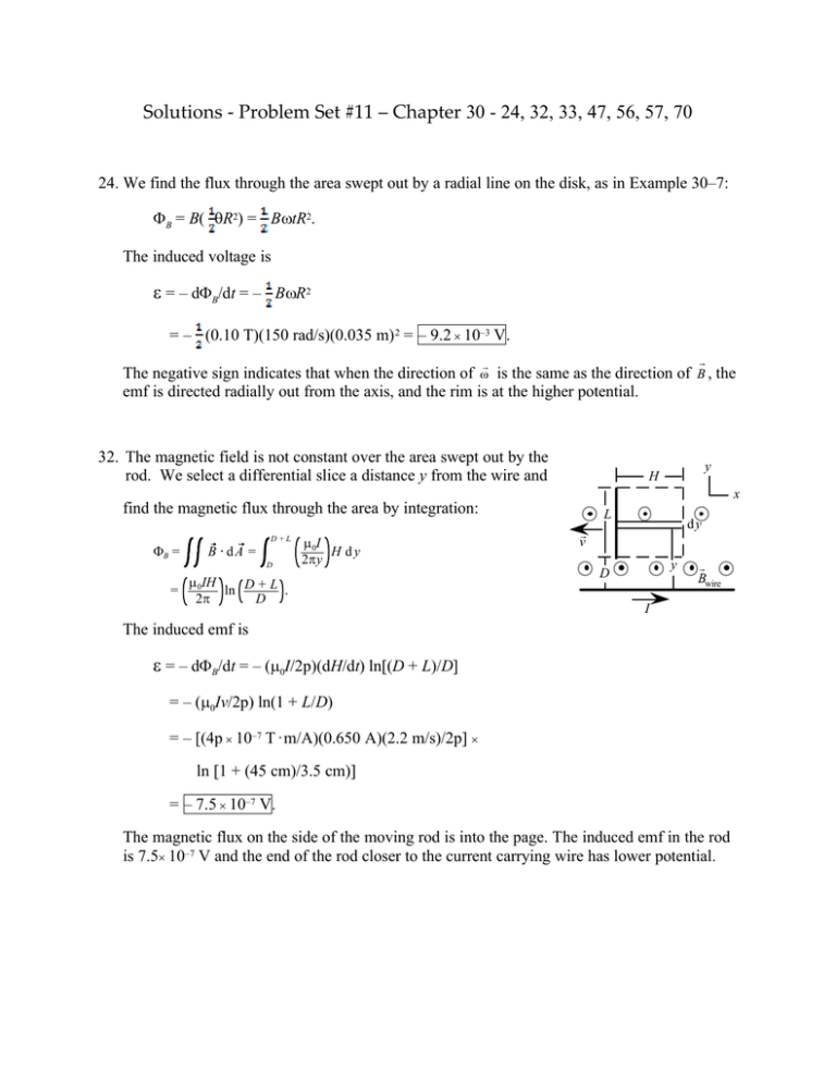
Solutions - Problem Set #11 – Chapter 30 - 24, 32, 33, 47, 56, 57, 70 24. We find the flux through the area swept out by a radial line on the disk, as in Example 30–7: ΦB = B( θR2) = BωtR2. The induced voltage is ε = – dΦB/dt = – BωR2 = – (0.10 T)(150 rad/s)(0.035 m) 2 = – 9.2 × 10⁻³ V. r r The negative sign indicates that when the direction of ω is the same as the direction of B , the emf is directed radially out from the axis, and the rim is at the higher potential. 32. The magnetic field is not constant over the area swept out by the rod. We select a differential slice a distance y from the wire and y H x find the magnetic flux through the area by integration: ΦB = D+L B · dA = D µ 0I H dy 2πy µ IH = 0 ln D + L . 2π D L dy r v y D r Bwire I The induced emf is ε = – dΦB/dt = – (µ0I/2p)(dH/dt) ln[(D + L)/D] = – (µ0Iv/2p) ln(1 + L/D) = – [(4p × 10–7 T · m/A)(0.650 A)(2.2 m/s)/2p] × ln [1 + (45 cm)/3.5 cm)] = – 7.5 × 10⁻⁷ V. The magnetic flux on the side of the moving rod is into the page. The induced emf in the rod is 7.5× 10⁻⁷ V and the end of the rod closer to the current carrying wire has lower potential. 33. We find the current in the loop from I = – (dΦB/dt )/R. Because the straight section is perpendicular to both the magnetic field and the velocity, the drag force is F = IBL = (dΦB/dt )BL/R = (17 T · m2/s)(0.16 T)(0.12 m)/(25 Ω) = 1.3 × 10⁻² N. The force to keep the loop moving must have the magnitude of the drag force, so the power is P = Fv = (1.3 × 10⁻² N)(35 m/s) = 0.46 W. 47. (a) The induced emf in the loop due to the change in current in the solenoid is ε = – dΦB / dt = – d(BA)/ dt = – A (dΒ/ dt) = – (πr2) d(µ0nI)/dt = – (πr2) µ0n (dI/dt) = – πr2µ0n (∆I/∆t) = – π(0.04 m)2(4π × 10–7 T · m/A)(1800/0.90 m)(1.2 A – 5 A)/0.3 s = 1.6 × 10⁻⁴ V. The induced current in the loop is then I = ε/R = (1.6 × 10⁻⁴ V) /(6 Ω) = 2.7 × 10⁻⁵ A. (b) Since the current in the solenoid decreases, the induced current in the loop flows in the same sense as the current in the solenoid. 56. A side view of the rail and wire is shown in the figure. When the wire is a distance s from the bottom, the magnetic flux through the loop is r r r r N r B r r FB ΦB = ?? B ⋅ d A = B · A = BLs cos θ. The induced emf is ε = – dΦB/dt = – (BL cos θ)(ds/dt) = – BL(– v) cos θ = BLv cos θ. This produces a current in the wire I = ε/R = (BLv cos θ)/R into the page. r mg s θ Because the current is perpendicular to the magnetic field, the force on the wire from the magnetic field will be horizontal, as shown, with magnitude FB = ILB = (B2L2v cos θ)/R. For the wire to slide down at a steady speed, the net force must be zero. If we consider the components along the rail, we have FB cos θ – mg sin θ = 0; [(B2L2v cos θ)/R] cos θ = (B2L2v cos2 θ)/R = mg sin θ; (0.68 T)2(1.2 m)2v(cos2 15°)/(2.0 Ω) = (65 × 10–3 kg)(9.8 m/s2) sin 15°, which gives v = 0.53 m/s. 57. (a) The magnetic field of the wire depends on the distance from the wire, B = (µ0/2p)I/y. When the moving rod is a distance x from the resistor, we select a differential slice a distance y from the wire and find the magnetic flux through the area by integration: ΦB = b B · dA = a µ 0I 0 x dy 2πy µIx b = 0 0 ln a . 2π The induced emf in the rod is I x y a b R r v ε = – dΦB/dt = – (µ0I/2p)(dx/dt) ln(b/a) = – (2 × 10⁻⁷ T · m/A)(150 A)(45 × 10–2 m/s) ln[(16 cm)/(8 cm)] = – 9.4 × 10⁻⁶ V (up). (b) To oppose the increase in flux into the page, the induced current in the loop will be counterclockwise, with magnitude Iind = ε/R = (9.4 × 10⁻⁶ V)/(0.20 Ω) = 4.7 × 10⁻⁵ A = 47 µA. (c) We find the time for the rod to move 100 cm from ? t = ? x/v. The rate at which work is done on the rod must equal the Joule heating. The work done in ? t is W = P ? t = Iind2R ? t = (4.7 × 10⁻⁵ A)2(0.20 Ω)(1.00 m)/(45 × 10–2 m/s) = 9.7 × 10⁻¹⁰ J. The work must be done by an external force applied to the rod. The small value means that the presence of any friction would require much more work by the external force. 70. As the bar moves forward it generates an induced emf, ε = BLv, so a current I = ε/R = BLv/R runs through it, and the bar is therefore subject to a magnetic force of magnitude F = BIL = B(BLv/R)L = (BL)2 v/R, which is against the direction of motion. The equation of motion of the bar is then m dv/dt = – (BL)2 v/R, or dv/dt = – [(BL)2/mR] v. Rewrite this as dv/v = – [(BL)2/mR] dt and integrate over both sides: ? dv/v = – [(BL)2/mR] ?dt ; ln (v/v0) = – [(BL)2/mR] t ; so v = v0 e –αt, where α = – (BL)2/mR .
