CASE STUDY
Operator Maintains 5-ft Drilling Target Window
for 6,890-ft Horizontal Well Offshore Australia
Real-time steering delivers optimal exposure to good-quality reservoir sands
CHALLENGE
Drill within narrow target zone in a challenging horizontal well
Minimize attic oil and avoid the oil/water
contact (OWC) in a horizontal well up to
6,890 ft [2,100 m] long by steering and
maintaining the wellbore 5–10 ft [1.5–3 m]
below the top of the reservoir.
An operator in Australia wanted to maximize exposure to good-quality sands in thinner oil columns
and drill longer horizontal trajectories, up to 6,890 ft [2,100 m], offshore Australia. It set a target
window of drilling 5–10-ft [1.5–3-m] TVD below the reservoir top to minimize attic oil production and
avoid the OWC. The wellbore would have to be maintained within the target window for the length of
the 6,890-ft [2,100-m] well section. However, the lower net sand and interbedded nature of the field
presented reservoir steering challenges.
SOLUTION
Use the GeoSphere* reservoir
mapping-while-drilling service to drill
a 6,890-ft [2,100-m] horizontal well
in narrow target window.
RESULTS
■■
■■
■■
Optimized the steering window on the
basis of mapping-while-drilling information
used to evaluate the oil column.
Maximized exposure to good-quality
reservoir sands, avoided the OWC, and
minimized attic oil by drilling in the
target window.
Determined that the layers dipped 3°–5°.
Use real-time mapping to find good-quality reservoir sands and drill on target
The operator selected the GeoSphere reservoir mapping-while-drilling service, which extends
the depth of investigation to more than 100 ft [30 m] and provides highly detailed information for
subsurface reservoir layers and fluid contacts. Using deep, directional electromagnetic measurements,
the service maps reservoirs, enabling operators to adjust drilling plans and drill on target in complex
downhole environments.
Optimized drilling plan and maintained trajectory in sweet spot
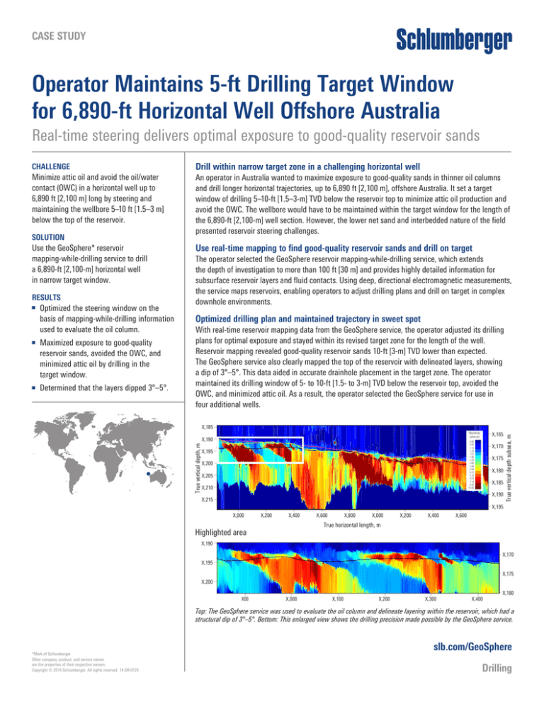
With real-time reservoir mapping data from the GeoSphere service, the operator adjusted its drilling
plans for optimal exposure and stayed within its revised target zone for the length of the well.
Reservoir mapping revealed good-quality reservoir sands 10-ft [3-m] TVD lower than expected.
The GeoSphere service also clearly mapped the top of the reservoir with delineated layers, showing
a dip of 3°–5°. This data aided in accurate drainhole placement in the target zone. The operator
maintained its drilling window of 5- to 10-ft [1.5- to 3-m] TVD below the reservoir top, avoided the
OWC, and minimized attic oil. As a result, the operator selected the GeoSphere service for use in
four additional wells.
True vertical depth, m
– X,165
Resistivity
(ohm.m)
X,190 –
0.80
0.95
1.12
1.33
1.57
1.86
2.20
2.60
3.08
3.64
4.31
5.10
6.03
7.14
8.45
10.00
X,195 –
X,200 –
X,205 –
X,210 –
– X,170
– X,175
– X,180
– X,185
– X,190
X,215 –
True vertical depth subsea, m
X,185 –
– X,195
X,000
X,200
X,400
X,600
X,800
X,000
X,200
X,400
X,600
True horizontal length, m
Highlighted area
X,190 –
– X,170
X,195 –
– X,175
X,200 –
X00
X,000
X,100
X,200
X,300
X,400
– X,180
Top: The GeoSphere service was used to evaluate the oil column and delineate layering within the reservoir, which had a
structural dip of 3°–5°. Bottom: This enlarged view shows the drilling precision made possible by the GeoSphere service.
*­ Mark of Schlumberger
Other company, product, and service names
are the properties of their respective owners.
Copyright © 2014 Schlumberger. All rights reserved. 14-DR-0124
slb.com/GeoSphere
Drilling


