2.1 Electrostatic Parallel Plate Actuators The simplest electrostatic
advertisement

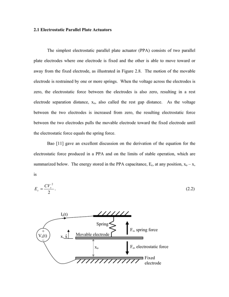
2.1 Electrostatic Parallel Plate Actuators The simplest electrostatic parallel plate actuator (PPA) consists of two parallel plate electrodes where one electrode is fixed and the other is able to move toward or away from the fixed electrode, as illustrated in Figure 2.8. The motion of the movable electrode is restrained by one or more springs. When the voltage across the electrodes is zero, the electrostatic force between the electrodes is also zero, resulting in a rest electrode separation distance, xo, also called the rest gap distance. As the voltage between the two electrodes is increased from zero, the resulting electrostatic force between the two electrodes pulls the movable electrode toward the fixed electrode until the electrostatic force equals the spring force. Bao [11] gave an excellent discussion on the derivation of the equation for the electrostatic force produced in a PPA and on the limits of stable operation, which are summarized below. The energy stored in the PPA capacitance, Ec, at any position, xo – x, is 2 Ec = CV s . 2 (2.2) Is(t) Spring + Vs_(t) . x, x Fs, spring force Movable electrode xo Fe, electrostatic force Fixed electrode Figure 2.8. An illustration of an electrostatic parallel plate actuator. Substituting (2.1) into (2.2) yields Ec = ε o ε r AVs 2 2d . (2.3) However, since d = xo + x (2.4) then Ec = ε o ε r AVs 2 2( x o + x ) . (2.5) If the top electrode is allowed to move an infinitesimally small distance, Δx, toward the bottom electrode while the voltage across the electrodes, Vs(t), is held constant, the actuator will gain energy and the power supply will give up internal energy. Therefore the energy balance equation becomes Fe Δx = dE p dE c Δx − Δx , dx dx (2.6) where FeΔx equals the energy gained by the PPA capacitance minus the internal energy lost by the power supply. By dividing both sides of (2.6) by Δx, the equation for Fe can be simplified to Fe = dE c dE p − , dx dx (2.7) where dE c Vs2 ∂C ( x) Vs2 ε o ε r A = =− dx 2 ∂x 2( xo + x) 2 (2.8) and dE p dx = Vs ∂q ( x) . ∂x (2.9) But since q ( x) = C ( x)Vs , (2.10) therefore dE p dx = Vs2 V 2ε ε A ∂C ( x) =− s o r 2 . ∂x ( xo + x) (2.11) Substituting the results of (2.9) and (2.11) into (2.7) yields the equation for the electrostatic force Fe = − Vs2 ε o ε r A Vs2 ε o ε r A Vs2 ε o ε r A + = . 2( xo + x) 2 ( xo + x) 2 2( xo + x) 2 (2.12) Observe that the electrostatic force is proportional to the drive voltage squared, but it is also inversely proportional to the electrode separation distance squared. Referring back to the illustration of a simple PPA in Figure 2.8, where the movable electrode has a mass, m, and the mechanical system has damping which can be modeled by c, the equation describing the system dynamics is m&x& + cx& + kx = − Fe . (2.13) The negative sign in front of Fe results from the definition that a positive electrostatic force results in a movable electrode motion in the negative x direction, as defined in Figure 2.8. After a small constant nonzero voltage, Vs, has been applied to the actuator and the movable electrode velocity has decayed to zero, the resulting force balance equation is kx = − ε o ε r AVs2 2( x o + x) 2 , (2.14) where k is the system spring constant. If the applied voltage is slowly increased from zero, two solutions exist for x, which yield two equilibrium points, one stable and one unstable. For an applied voltage just greater than zero, the stable equilibrium point resides almost at x = 0, while the unstable equilibrium point resides almost at the x = xo. As the voltage is further increased, the two equilibrium points move toward each other and finally converge into one unstable equilibrium point. This equilibrium point convergence occurs when the electrode separation distance equals one third of the rest gap distance, xo. The voltage at which this occurs is called the pull-in voltage, Vpi, where V pi = 8kxo3 . 27ε o ε r A (2.15) A voltage equal to or greater than Vpi results in an unstable condition where the movable electrode snaps into contact with the fixed electrode. This occurs because the spring force is now always less than the electrostatic force. Therefore for open loop operation, the PPA range of motion is limited to less than one third of xo. Several techniques have been developed to increase the stable operating range of motion, but they usually result in a penalty such as higher required operating voltage [12, 13].


