International Journal of
Emerging Research in Management &Technology
ISSN: 2278-9359 (Volume-4, Issue-6)
Research Article
June
2015
Diagnosis of Commutation Failure in HVDC Transmission
System Using Matlab
1
Amita, 2Ramavtar Jaswal
M.Tech (EE), UIET Kurukshetra University, Kurukshetra, Haryana, India
2
Assistant Professor, Department of EE, UIET, Kurukshetra University, Haryana, India
1
Abstract:
C
ommutation failure problem is normal in hvdc system .In this paper we study how we mitigate the problem
of commutation failure .Fast diagnosis of commutation failure in HVDC systems can improve the level of
operation in the power systems.. The abc-αβ transformation is used for three-phase fault detection, and the
zero-sequence voltage, is used for single phase fault detection. when ac faults occurs control system operate very
quickly because both detection methods are based on the instantaneous values.Fast diagnosis of commutation
failurein HVDC systems can improve the level of operation in the power systems. An additional angle is deducted
from the firing order at the inverter station after detecting the fault , that increase the commutation margin .By this
method we effetely reduce the commutation failure risk.
Index Terms: Commutation failures, voltage dips, power system faults, HVDC transmission
I. INTRODUCTION
Commutation failure are very common dynamic events in high voltage dc (HVDC) transmission systems . Failure to
complete commutation before the commutating voltage reverses is referred as commutation failures. Commutation
failures occur in HVDC systems due to ac voltage dips (possibly caused by an ac systems shortcircuit), increased direct
current, late ignition or a combination of these. The inverter is more prone to commutation failure. The sensitivity of an
HVDC inverter to commutation failures depends on the specific main circuit design and on the control system. It is
reported that commutation failures may happen during an ac system disturbance, where the voltage reduction is only as
small as 10% and due to this overlapping angle increases. Over current flow in valve due to repeated commutation failure
and after clearing of fault ,it delay the restart time .Sometime blocking of valve takes place. Commutation failures happen
if the commutation of current from one valve to another has not been completed before the commutating voltage reverses
across the ongoing valve. This results in a short circuit across the valve group. The basic reason for commutation failures
is that the extinction angle during system disturbance is too small. If we enlarge the commutation margin we can
mitigate commutation failure.
II. BASIC WORKING PRINCIPLE
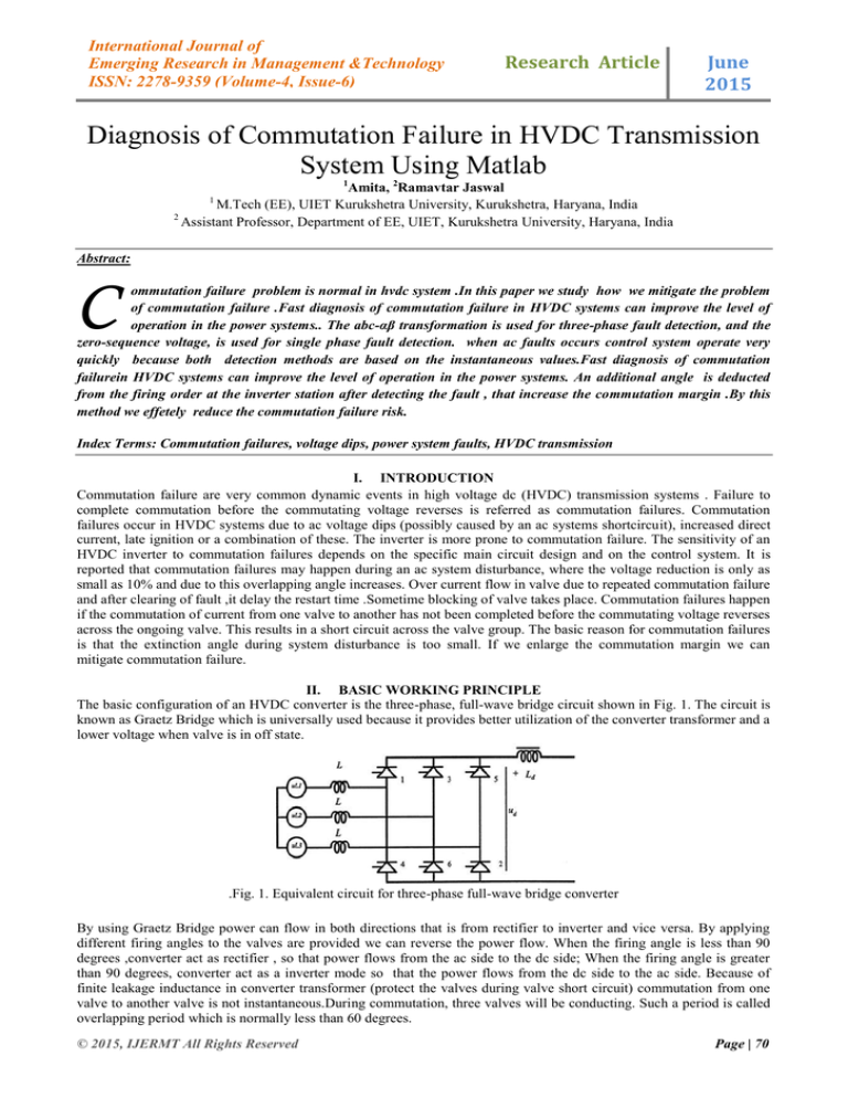
The basic configuration of an HVDC converter is the three-phase, full-wave bridge circuit shown in Fig. 1. The circuit is
known as Graetz Bridge which is universally used because it provides better utilization of the converter transformer and a
lower voltage when valve is in off state.
.Fig. 1. Equivalent circuit for three-phase full-wave bridge converter
By using Graetz Bridge power can flow in both directions that is from rectifier to inverter and vice versa. By applying
different firing angles to the valves are provided we can reverse the power flow. When the firing angle is less than 90
degrees ,converter act as rectifier , so that power flows from the ac side to the dc side; When the firing angle is greater
than 90 degrees, converter act as a inverter mode so that the power flows from the dc side to the ac side. Because of
finite leakage inductance in converter transformer (protect the valves during valve short circuit) commutation from one
valve to another valve is not instantaneous.During commutation, three valves will be conducting. Such a period is called
overlapping period which is normally less than 60 degrees.
© 2015, IJERMT All Rights Reserved
Page | 70
Amita et al., International Journal of Emerging Research in Management &Technology
ISSN: 2278-9359 (Volume-4, Issue-6)
Fig 2 converter bridge circuit with valves 1,2 and 3
Fig.3 commutation of current in valve 1 and 3
If suppose the valve 1 and valve 2 is conducting at an instant (figure 2), and valve 3 is fired
and starts conducting. But still valve 1 is conducting until the stored magnetic energy in the
converter transformer goes to zero. During the commutation Id is summation of i1 and i3, i1
is decreasing from Id to zero and i3 is increasing from 0 to Id (figure 3).Voltage drop due to overlapping angle can be
achieved by fig4
∆Ud= 6.f.L.Id =6.(ω/2 Π),L.Id
(1)
∆Ud = 3.(ω./Π).L.Id
(2)
Fig.4 direct voltage with effect of delay angle and overlapping angle
Since the current changes through the inductance is 6 times for 6-pulse converter
Fig. 5 rectifier direct voltage
Therefore, the total rectifier DC voltage will be
Ud=1.35.Ull.cosα-(3/Π).ω.L.Id
(3)
Fig.6 Inverter direct voltage
© 2015, IJERMT All Rights Reserved
Page | 71
Amita et al., International Journal of Emerging Research in Management &Technology
ISSN: 2278-9359 (Volume-4, Issue-6)
The inverter DC voltage will be found by
Ud=1.35.ULL.cosγ-(3/Π).ω.L.Id(4)
III. COMMUTATION FAILURE
Commutation failures in HVDC systems are mainly caused by voltage dips due to ac system faults .voltage dips may
cause both voltage magnitude reduction and phase-angle shift. Voltage dips may affect the commutation in following
way1) Voltage magnitude reduction
when there is a voltage dip commutating ac line-to-line voltage decreases, as shown in Fig.7 . Since the voltage
magnitude has decreased, here the commutation area still remain the same,and voltage magnitude has decreased so the
end of commutation will be delayed and the extinction angle will change from γ toϓ.It crosses its minimum limit.
Fig 7 voltage magnitude reduction
2) Increase in dc current
when fault occur at inverter end the dc current increases. Since the volt-time area increases with the increased dc current,
a relatively larger overlap μ will be needed to complete the commutation.This reduce the gamma value to its minimum
value.
Fig.8 Increase in dc current
THE DIAGNOSIS METHOD FOR COMMUTATION FAILURE:
When the extinction angle gamma reaches to its minimum due to voltage dips in ac systems commutation failures takes
place. To be able to keep a gamma in its normal limits, the control system should give an advanced firing instant on
detection of the ac system disturbance. It is not possible at all to avoid commutation failure at inverter when sudden
increase of dc current and decrease of commutating voltage. However, it could be possible to avoid subsequent
commutation failures during the high remaining voltage fault at inverter ac network by advancing the firing angle in
order to increase the commutation margin. This makes the system could transfer power during disturbance. There are two
possibilities for commutation failure such as commutation voltage reduction or distortion and phase angle jump at
unbalanced fault. Therefore, two different sets of control function used to avoid consecutive commutation failure caused
by balanced and unbalanced fault.
Fig.9 commutation failure prevention block
© 2015, IJERMT All Rights Reserved
Page | 72
Amita et al., International Journal of Emerging Research in Management &Technology
ISSN: 2278-9359 (Volume-4, Issue-6)
One parallel path is based on zero-sequence detection to detect single-phase faults, and the other one is based on abc-αβ
transformation to detect three-phase faults. This control module is called
CFPREV (Commutation Failure Prevention). Single-phase faults are the most frequently-occurring unbalanced faults
experienced by the HVDC converter. The three-phase voltages at the converter bus usually contain zero sequence voltage
during this type of fault. Z_DIFF is obtained simply by adding up three-phase instantaneous voltage as
U o= U a+ Ub+ U c
(4)
A MAX_HOLD function with is used to convert the sinusoidal wave shape into a dc quantity. The MAX_HOLD
function is so designed that it holds the maximum value it detects and maintains it for certain time , if no bigger value is
detected. If Z_DIFF is greater than a predefined level, the signal Z_AMIN from MAX_HOLD will be the angle that will
be deducted from the final firing angle .Another part is based on abc-αβ transformation to detect three-phase faults. The
idea of abc-αβ transformation is to use one rotating vector to represent three-phase voltages .following equation give
the expressions of Uα and Uβ used in CFPREV
Uα= (2/3)Ua-(1/3){Ua+Ub}
(5)
Uβ =(3/3){Ub -Uc}
(6)
Since the reduction of voltage at single phase fault is not severe as three phase fault, but creates phase shift. So the
unsymmetrical fault is detected by zero sequence voltage detection, then it compared with pre-defined voltage level, if
zero sequence voltage is lower than predefined level, it advances the firing angle and keeps it for whole fault duration.
Symmetrical fault will not give zero-sequence, therefore it directly compared with predefined value and voltage (prefault
voltage – fault voltage) difference, it will decrease the firing angle if the difference is higher than predefined value. In
brief, the three phase voltages are transformed to dc quantity by alpha-beta transformation; it gives dc output only when
the three phases are symmetrical. However, three phase fault will not decrease the voltage instantaneously in all the
phases, it decrease the voltage phase by phase hence creates negative sequence the same happens when clearing the fault.
Therefore, oscillations will occur in alpha-beta output. It is not possible to compare the oscillating waveform with prefault voltage, so max-hold function is used here to keep the maximum value for half cycle Although the above two parts
of the control module deal with different fault conditions, they might be activated at the same time. In such a situation,
the maximum value of Z_AMIN and ABZ_AMIN will be chosen as the final output of the entire control module. The
output AMIN_CFPREV value will be deducted from the final inverter firing control, advancing the firing instant and
leaving a bigger commutation margin.
IV.
SIMULATION AND TEST RESULTS
Simulation setup
A simulation model, as shown in Fig 10 , has been developed on Mat lab to study the effect of CFPREV in mitigating
commutation failures.
Fig.10 matlab simulation model
Test result:
To test the effect of the commutation failure prevention module (CFPREV), simulation tests were performed to induce
commutation failures during single-phase faults and three phase faults.
inverter bus voltage
1.5
1
voltage
0.5
0
-0.5
-1
-1.5
0.4
0.5
0.6
0.7
0.8
0.9
1
1.1
time
Fig. 11.Inverter bus voltages, during a single-phase fault at the inverter bus.
© 2015, IJERMT All Rights Reserved
Page | 73
Amita et al., International Journal of Emerging Research in Management &Technology
ISSN: 2278-9359 (Volume-4, Issue-6)
z diff
1
0.8
0.6
0.4
voltage
0.2
0
-0.2
-0.4
-0.6
-0.8
-1
0
0.2
0.4
0.6
0.8
1
1.2
1.4
1.6
1.8
2
time
Fig.12 Zdiff, during a single-phase fault at the inverter bus.
AMINCFPREV
25
20
Degree
15
10
5
0
0
0.2
0.4
0.6
0.8
1
1.2
1.4
1.6
1.8
2
Fig.13 AMIN CFPREV during a single-phase fault at the inverter bus.
Fig. 11,12,13 shows the inverter bus voltages, Z_DIFF, AMIN_CFPREV during a single-phase fault with 20% remaining
voltage at the faulted phase. When the fault is applied at 0.7 second, the voltage at the faulted phase drops immediately.
The zero-sequence voltage comes up because the three phases are no longer symmetrical. As we have noticed, the zerosequence voltage is a sinusoidal curve, whose magnitude depends on how high the remaining voltage is at the faulted
phase. The MAX_HOLD item maintains the maximum value of Z_DIFF for some time, which converts the sinusoidal
curve to a flat curve. The signal AMIN_CFPREV is the final output from CFPREV to the main control system at the
inverter station. The contribution AMIN_CFPREV of CFPREV is deducted from the final inverter firing angle.
Waveform during three phase fault :
1.5
1
inverter bus voltage(p.u)
0.5
0
-0.5
-1
-1.5
0.7
0.75
0.8
0.85
0.9
0.95
time(s)
Fig 14.Inverter bus voltages during a three-phase fault at the inverter bus.
ALPHA BETA SUM
1.5
P.U
1
0.5
0
0
0.1
0.2
0.3
0.4
0.5
0.6
0.7
0.8
0.9
1
TIME
Fig 15. ALPHA BETA SUM during a three-phase fault at the inverter bus.
25
20
Degree
15
10
5
0
0
0.1
0.2
0.3
0.4
0.5
0.6
0.7
0.8
0.9
1
Fig 16 AMIN CFPREV during a three-phase fault at the inverter bus.
V.
CONCLUSIONS
This paper presents a novel fault diagnosis method of commutation failure in HVDC system . It has been shown by the
simulation model that this method is very effective in reducing the possibility of commutation failures from single phase
fault and three phase fault at the inverter..
© 2015, IJERMT All Rights Reserved
Page | 74
Amita et al., International Journal of Emerging Research in Management &Technology
ISSN: 2278-9359 (Volume-4, Issue-6)
REFERENCES
[1]
E.W.Kimbark, Direct Current Transmission, vol.I, Wiley-Interscience, 1971.
[2]
C.V.Thio, J.B.Davies, K.L. Kent, “Commutation failures in HVDC transmission systems”, IEEE Trans. Power
delivery, vol.11, pp.946-957, Apr. 1996.
[3]
L.D. Zhang, M.H.J. Bollen, Characteristic of voltage dips (sags) in power systems, IEEE Trans. Power delivery,
Vol.15, pp.827 832, April 2000.
[4]
A.Hansen, H.Havemann, “Decreasing the commutation failure frequency in HVDC transmission systems”,
IEEE Trans. Power delivery, vol.15, pp.1022-1026, July 2000.
[5]
G. Gudmundsson, M. Wik, “HVDC converter commutation failure prevention”, Master thesis, Dalarna
Hogskola, E1370E, May 1998.
[6]
Sweezy, A. George, “HVDC inverter commutation failure prevention control utilizing sequence voltage
detection”, Technical report from ASEA power systems center, USA, TR-PSC-86-033, 1986.
© 2015, IJERMT All Rights Reserved
Page | 75


