ω ω ω
advertisement

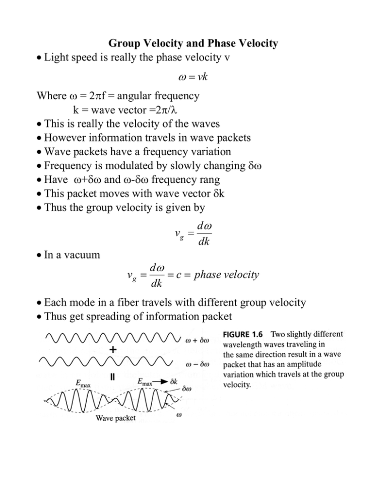
Group Velocity and Phase Velocity • Light speed is really the phase velocity v ω = vk Where ω = 2πf = angular frequency k = wave vector =2π/λ • This is really the velocity of the waves • However information travels in wave packets • Wave packets have a frequency variation • Frequency is modulated by slowly changing δω • Have ω+δω and ω-δω frequency rang • This packet moves with wave vector δk • Thus the group velocity is given by vg = • In a vacuum vg = dω dk dω = c = phase velocity dk • Each mode in a fiber travels with different group velocity • Thus get spreading of information packet Multi Mode and Single Mode Fiber • Multi mode fiber results in spreading of signal • But number of modes is set by core diameter and index • Can change number of modes by changing these • Want a single mode fiber m=0 • Number of modes are set by (2V − φ ) m≤ π • Where V is the V number given by V= 2π a λ n12 − n22 • Thus get a single mode when V<π/2 • To create single mode make diameter of core very small • Result much reduced pulse spreading • Multi mode fiber 380 μm diameter with 200 μm core • Single mode 125 μm diameter with 10 μm core • Also in indexes much smaller Acceptance Angle and Fibers • Problem with single mode is harder to get signal into fiber • Called coupling with the fiber • Acceptance angle θa = αmax max angle light can enter fiber sin(θ a ) n1 = sin(90o − θ c ) n0 sin( θ c ) = • Thus n12 − n22 NA sin( θ a ) = = n0 no • The fiber’s Numerical Aperture is NA = n12 − n22 • Total Acceptance Angle is 2θa n2 n1 Single & Multi-Mode Fiber Acceptance • Multimode fiber example • n1=1.480, n2 = 1.460 with a core of 200 μm NA = n12 − n22 = 1.4802 − 1.4602 = 0.2425 ⎛ NA ⎞ 0.2425 ⎞ o ⎟⎟ = arcsin⎛⎜ ⎟ = 14 ⎝ 1 ⎠ ⎝ no ⎠ • And total acceptance angle is 28o • Now consider a single mode fiber • n1=1.460, n2 = 1.464 (only 0.3% larger) with a core of 10 μm θ a = arcsin⎜⎜ NA = n12 − n22 = 1.460 2 − 1.464 2 = 0.0.113 ⎛ NA ⎞ 0.113 ⎞ o ⎟⎟ = arcsin⎛⎜ ⎟ = 6 .5 ⎝ 1 ⎠ ⎝ no ⎠ • Thus much harder to couple light θ a = arcsin⎜⎜ Graded Index (GRIN) Fiber • Due to small acceptance angle want alternative to single mode • Uuse a GRaded INdex in the core (GRIN) • Made by doping fiber with material that varies with postion • Light now bends rather than reflects • Get acceptance angle close to multimode • But bit rate much higher than multimode Fiber Dispersion and Bit Rate • Dispersion of pulse in fiber sets the limit of bit rate • Look at the Full Width Half Power (FWHP) of signal Δτ1/2 • Two pulse must be at least 2Δτ1/2 apart to be separated • Bit rate is thus 1 B≅ 2Δτ 1 / 2 • Δτ1/2 increase with distance so measure • Dispersion = Bandwidth x distance Comparison of Multimode, GRIN and Single Mode • Multi mode: high acceptance angle • High dispersion ~20-100 Mhz km bandwidth product • Can use LED’s for emitters • Easy to install – used for short distance networks • GRIN acceptance angle near multimode: easy to connect • Medium dispersion ~300 MHz km bandwidth product • LED or lasers as emitters • Medium distance networks • Single mode small acceptance angle • Thus harder to interconnect fibers • Low dispersion 100 GB/s in field • Laser diodes needed for narrow wavelength Fiber Bending Loses • When fiber is bent or has imperfection get increased loss • Due to change in light angle to below critical angle • Lose Total Internal Reflection • The effective absorption coefficient αB increases greatly • Smaller radius of curvature, larger the light leaking out How Fiber is Made • Fiber starts with rod of core and cladding • Heated in drawing furnace- often rotated to make even • Pulled into a narrow fiber • Monitor fiber diameter – adjusted with pull rate • Add plastic coating on outside • Rolled into spool


