Application Note
AN-113 Rev A
Pulling Measurement of Z-COMM VCOs
The pulling response of Z-COMM VCOs is directly affected by improper matching and insufficient isolation.
The frequency variation due to load mismatching is defined as pulling. Measured pulling performance of ZCOMM VCOs can be verified using the pulling test setup and procedure described in the following.
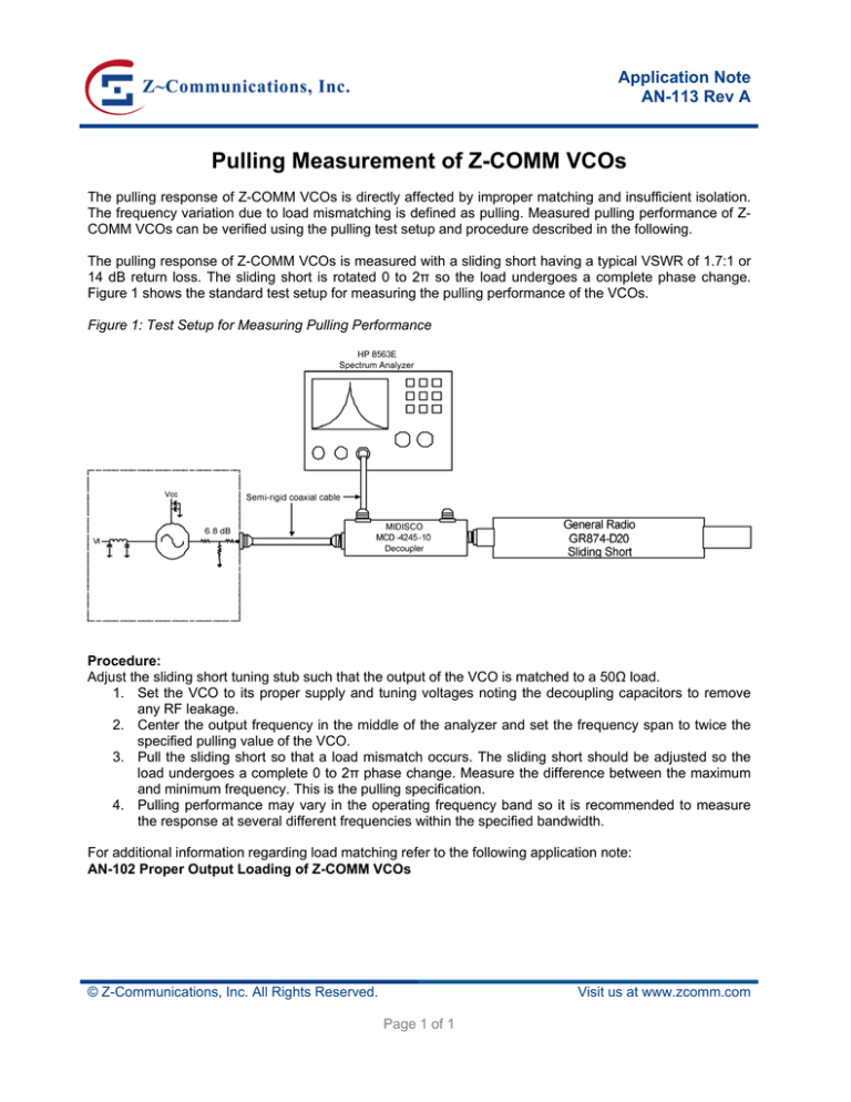
The pulling response of Z-COMM VCOs is measured with a sliding short having a typical VSWR of 1.7:1 or
14 dB return loss. The sliding short is rotated 0 to 2π so the load undergoes a complete phase change.
Figure 1 shows the standard test setup for measuring the pulling performance of the VCOs.
Figure 1: Test Setup for Measuring Pulling Performance
Procedure:
Adjust the sliding short tuning stub such that the output of the VCO is matched to a 50Ω load.
1. Set the VCO to its proper supply and tuning voltages noting the decoupling capacitors to remove
any RF leakage.
2. Center the output frequency in the middle of the analyzer and set the frequency span to twice the
specified pulling value of the VCO.
3. Pull the sliding short so that a load mismatch occurs. The sliding short should be adjusted so the
load undergoes a complete 0 to 2π phase change. Measure the difference between the maximum
and minimum frequency. This is the pulling specification.
4. Pulling performance may vary in the operating frequency band so it is recommended to measure
the response at several different frequencies within the specified bandwidth.
For additional information regarding load matching refer to the following application note:
AN-102 Proper Output Loading of Z-COMM VCOs
© Z-Communications, Inc. All Rights Reserved.
Visit us at www.zcomm.com
Page 1 of 1

