Measurement & Modeling
Device Characterization Solutions
A Beginner's Guide To All Things Load Pull
ARTICLE REPRINT
March 2015
OR Impedance Tuning 101
Author: Gary Simpson, Chief Technology Officer, Maury Microwave Corporation, Ontario, California.
This reprint is based on an article that original appeared in Microwaves&RF magazine – digital edition of 1 December,
2014. It can be found online at http://mwrf.com/test-measurement/impedance-tuning-101
ABSTRACT ­­— Load pull is an essential tool in the design, test, model validation process of amplifier development and is also used
in test validation of various system modules. There are different methods to perform load pull and based on customer requirement,
one of these methods is presented. This article is intended to introduce the basics of load pull and tools needed to accomplish this
measurement method.
Non-50ohm Measurements
Slide-Screw Tuners
Non-50ohm measurements have become a hot topic over the
past few years, with techniques being used for amplifier design,
model extraction, model validation, performance and ruggedness
testing and more. For a beginner, so much information might
seem overwhelming, and a basic introduction to non-50ohm
measurement concepts and the need for such measurements
would be extremely helpful. You’ve asked, we’ve answered…
introducing a beginner’s guide to all things “load pull”.
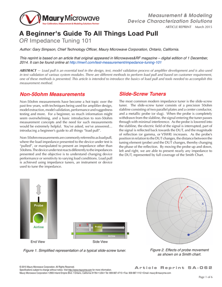
The most common modern impedance tuner is the slide-screw
tuner. The slide-screw tuner consists of a precision 50ohm
slabline consisting of two parallel plates and a center conductor,
and a metallic probe (or slug). When the probe is completely
withdrawn from the slabline, the signal entering the tuner passes
through with minimal interference. As the probe is lowered into
the slabline, the electric field of the signal is interrupted, part of
the signal is reflected back towards the DUT, and the magnitude
of reflection (or gamma, or VSWR) increases. As the probe’s
position in relation to the DUT changes, the distance between the
tuning element (probe) and the DUT changes, thereby changing
the phase of the reflection. By moving the probe up and down,
left and right, we are able to present nearly any impedance to
the DUT, represented by full coverage of the Smith Chart.
Non-50ohm measurements are commonly referred to as load pull,
where the load impedance presented to the device under test is
“pulled”, or manipulated to present an impedance other than
50ohms. The device under test reacts differently to the impedances
presented and the objective is to understand changing device
performance or sensitivity to varying load conditions. Load pull
is achieved using impedance tuners, an instrument or device
used to tune the impedance.
End View
Side View
Figure 1. Simplified representation of a typical slide-screw tuner.
Figure 2. Effects of probe movement
as shown on a Smith chart.
© 2015 Maury Microwave Corporation. All Rights Reserved.
Article Rep
Specifications subject to change without notice. Visit http://www.maurymw.com for more information.
Maury Microwave Corporation • 2900 Inland Empire Blvd. • Ontario, California 91764 • USA • Tel: 909-987-4715 • Fax: 909-987-1112 • Email: maury@maurymw.com
rint 5A-062
Page 1 of 6
Measurement & Modeling
Device Characterization Solutions
ARTICLE REPRINT March 2015
Automated Slide-Screw Tuner
An automated slide-screw impedance tuner works exactly like its
manual cousins, except instead of relying on hand positioning,
motors are used to move and position the probe with extreme
precision. Automation allows us to pre-calibrate (pre-characterize)
the tuner. Pre-calibration is the association of scattering parameters
(s-parameters) to physical X- and Y-positions of the probe, thereby
creating a lookup table to be used in determining how to present
an impedance to the DUT. A calibrated VNA and automated
software are used to measure the s-parameters as a function of
probe position, and positions are usually chosen to fully enclose
the Smith Chart.
Figure 3. An automated slide-screw impedance tuner setup with a calibrated VNA and automated software.
Uses of Tuners
Traditional (Scalar) Load Pull
There are many uses of modern impedance tuners, and in general
offer an efficient method to design and test your designs at the
component level, circuit level or system level. Impedance
tuners can be used to determine the ideal matching impedance
for power, gain, efficiency, noise figure or other parameters in
amplifier design. They can be used to build models, taking non50ohm measurements and incorporating them into a compact,
database or behavioral model. They can be used to validate
models, comparing simulated performance results against actual
measured data. They can be used to test the performance of a
matched DUT as a function of mismatch, measuring the drop in
performance as the match is tuned away from 50ohm. It can be
used to test finished systems such as mobile phones, radios and
transceivers. One simple tool, so versatile.
Traditional scalar load pull uses automated impedance tuners to
tune the impedance presented to the source and/or load of the
DUT, and uses a scalar power meter as the central measurement
instrument. Power is measured at the power sensor reference
plane, and mathematically de-embedded to the DUT reference
plane taking into account the passive losses between the power
sensor and the DUT, including the loss of the tuner which changes
as a function of impedance/probe position. The power sensor is
wideband, and measures all power including the fundamental
and harmonic frequencies. A spectrum analyzer (or multiplexer
with several power sensors) can be added in order to read specific
powers at each frequency as well as powers at intermodulation
frequencies if driven by a two-tone signal. Depending on the
signal source and analyzer, CW, pulsed-CW, single-tone, twotone and/or modulated signals, and their respective measurement
parameters, may be achievable.
© 2015 Maury Microwave Corporation. All Rights Reserved.
Article Rep
Specifications subject to change without notice. Visit http://www.maurymw.com for more information.
Maury Microwave Corporation • 2900 Inland Empire Blvd. • Ontario, California 91764 • USA • Tel: 909-987-4715 • Fax: 909-987-1112 • Email: maury@maurymw.com
Page 2 of 6
rint 5A-062
Measurement & Modeling
Device Characterization Solutions
ARTICLE REPRINT March 2015
Figure 4. Traditional (scalar) load pull block diagrams.
Vector-Receiver Load Pull
Vector-receiver load pull uses the same automated impedance
tuners to tune the impedance presented to the source and/or
load of the DUT. However, instead of using a scalar power
meter to measure scalar powers, a vector-receiver (normally of
a vector network analyzer, VNA) is used to measure the vector
a- and b-waves at the DUT reference plane. This is achieved
by connecting the direct receiver access of the VNA to low-loss
couplers placed between the tuners and DUT and calibrating
the system at the DUT reference plane. A1, b1, a2 and b2 are
measured for each frequency, and from these vectors we are
able to calculate available and delivered input power, output
power, transducer and power gain, efficiency and true power
added efficiency. Additionally, because we are calibrated at
the DUT, we can measure the large signal input impedance in
real-time, monitor for oscillations (gamma in>1) and measure
the mismatch to calculate actual delivered power to the input
of the DUT. We can also look into the tuners and measure
the impedance presented to the DUT, not relying on the precalibrated (pre-characterized) impedances and losses. And since
the measurements are made at the DUT reference, there is no
mathematical de-embedding (eliminates a source of measurement
error). Signals include CW or pulsed-CW, single-tone or twotone with their respective measurement parameters (by default
measured on a frequency-by-frequency basis given the a- and
b-waves are frequency dependent).
Some modernVNAs are capable of Nonlinear-VNA measurements
(NVNA) including time-domain voltage and current waveforms
and load lines, which can be useful for studying classes of
operation. Vector-receiver load pull can be easily extended to
NVNA-based load pull (as long as the VNA can perform NVNA
measurements, so can the load pull system).
Figure 5. Vector-receiver load pull block diagram.
© 2015 Maury Microwave Corporation. All Rights Reserved.
Article Rep
Specifications subject to change without notice. Visit http://www.maurymw.com for more information.
Maury Microwave Corporation • 2900 Inland Empire Blvd. • Ontario, California 91764 • USA • Tel: 909-987-4715 • Fax: 909-987-1112 • Email: maury@maurymw.com
rint 5A-062
Page 3 of 6
Measurement & Modeling
Device Characterization Solutions
ARTICLE REPRINT March 2015
Active and Hybrid-Active Load Pull
As discussed earlier, passive load pull can be achieved by using a
mechanical slide-screw tuner to partially reflect part of the signal
back towards the output of the DUT. In reality, the impedance
presented to the DUT, gamma, load, is the ratio between the
reflected signal a2 and the forward traveling signal b2. Hence by
adjusting the probe of the tuner, we are changing the magnitude
and phase of the reflected a2 signal and therefore changing the
magnitude and phase of the impedance presented to the DUT.
With active load pull, instead of using a passive tuner to reflect
the signal back towards the DUT, the signal is either adjusted in
magnitude and phase and recirculated (closed-loop active load
pull) or terminated and a new signal is introduced back towards
the DUT (open-loop active load pull).
Closed-loop active load pull has the benefits of not requiring
a separate signal source for injection, and starting at a higher
power signal (Pout of DUT) before amplification. Disadvantages
include the possibility of oscillations due to the close-loop nature
of the RF circuit.
Open-loop active load pull has the benefits of being easy to
implement and control and safe from most oscillations, however
is requires the addition of signal sources and larger amplifiers to
achieve the desired results.
Open-loop active load pull is currently the more popular approach
due to its robustness and ease of implementation. Active load
pull can be used to replace a passive tuner, or used to enhance
a system containing tuners. When placed behind a load tuner,
active load pull can act in enhancement mode, adding to the
reflected power of the passive tuner and achieving a higher gamma.
Additionally, it can be easily used to add harmonic impedance
control when combined with passive tuners, or used independently
for harmonic load pull with multiple active tuning loops.
Figure 6. A typical configuration for passive load pull (a),
compared with a typical closed-loop configuration (b), and
a typical open-loop configuration (c) for active load pull.
© 2015 Maury Microwave Corporation. All Rights Reserved.
Article Rep
Specifications subject to change without notice. Visit http://www.maurymw.com for more information.
Maury Microwave Corporation • 2900 Inland Empire Blvd. • Ontario, California 91764 • USA • Tel: 909-987-4715 • Fax: 909-987-1112 • Email: maury@maurymw.com
Page 4 of 6
rint 5A-062
Measurement & Modeling
Device Characterization Solutions
ARTICLE REPRINT March 2015
Mixed-Signal Active Load Pull
Mixed-signal active load pull is an extension of open-loop active
load pull, where a new signal is created to satisfy the equation
gamma=a2/b2. However instead of looking at a single frequency
(or a set of harmonic frequencies), we are looking at a wideband
set of frequencies covering the modulation bandwidth of a realistic
communication signal. By using wideband AWG and A/D, it is
possible to control the impedance presented to the DUT over
a bandwidth of up to 240 MHz. As such, active load pull can
be extended to modulated signals as well as single-tone and
two-tone CW and pulsed-CW signals, and can compensate for
phase-delay effects introduced into measurement systems that
might degrade RF performance.
The wideband signal generation and analysis can also be used
with single-tone signals, where the signal is divided in time, and
the record which would contain the wave modulation for a single
modulated impedance can contain several wave magnitudes
and phases representing many single-tone impedances. In this
manner, it is possible to load pull 1000 impedance/power states
per minute.
Figure 7. Principle of the mixed-signal load pull setup as a signal-flow diagram.
Figure 8. Injection signals as used in the "real-time" multi-dimensional parameter sweeps.
© 2015 Maury Microwave Corporation. All Rights Reserved.
Article Rep
Specifications subject to change without notice. Visit http://www.maurymw.com for more information.
Maury Microwave Corporation • 2900 Inland Empire Blvd. • Ontario, California 91764 • USA • Tel: 909-987-4715 • Fax: 909-987-1112 • Email: maury@maurymw.com
rint 5A-062
Page 5 of 6
Measurement & Modeling
Device Characterization Solutions
ARTICLE REPRINT March 2015
Harmonic Load Pull
Biasing a Device for Load Pull
Harmonic load pull is an extension of load pull, in which not
only the fundamental frequency impedance is controlled, but
also harmonic frequency impedances. The methodology used
to perform harmonic load pull can differ based on the load pull
methodology (traditional vs. vector-receiver). Passive harmonic
load pull can be as simple of using multiple tuners, one for each
frequency, whose effects are separated by a multiplexer, so that
each tuner has a narrowband effect only at its frequency of interest.
In most cases, any DC power supply can be used to bias a DUT. In
some cases, it is good enough to use a constant DC bias, however
there are instances in which it might be less than ideal. When
a device is driven with a pulsed-CW signal, the current-drawn
from the supply will be modulated with the RF pulse; in this case
it is important to measure the bias at the peak of the pulse using
an oscilloscope. Another option is to use a forced pulsed-bias
to apply the bias only during the on-time of the RF signal. This
not only eliminates the possible need of an oscilloscope (if the
pulsed supply has its own measurement capability), but the
overall temperate of the DUT remains lower and can be useful
for avoiding self-heating phenomena.
A second passive method involves cascading tuners, either
internally or externally, so that the number of tuning probes
equals the number of controlled harmonic frequencies. In this
case, mathematics are used to determine unique positions of the
various probes such that the vector addition at all frequencies
results in the requested impedances.
Harmonic load pull can also be achieved through active tuning
as explained earlier, with an active tuning source dedicated to
each frequency, and the injected a2 wave at each harmonic
frequency being set to satisfy the gamma@nF=a2@nf/b2@nf.
Summary
Load pull is an essential tool in the design, test, model validation
process of amplifier development and is also used in test validation
of various system modules. There are different methods to
perform load pull and based on customer requirement, one of the
aforementioned methods is chosen. The details of each method
is an elaborate paper by itself, but this article aimed to introduce
just the basics of load pull and tools needed to accomplish this
measurement.
© 2015 Maury Microwave Corporation. All Rights Reserved.
Article Rep
Specifications subject to change without notice. Visit http://www.maurymw.com for more information.
Maury Microwave Corporation • 2900 Inland Empire Blvd. • Ontario, California 91764 • USA • Tel: 909-987-4715 • Fax: 909-987-1112 • Email: maury@maurymw.com
Page 6 of 6
rint 5A-062


