Standard colors KMS IA23 ECU wiring loom For more information
advertisement
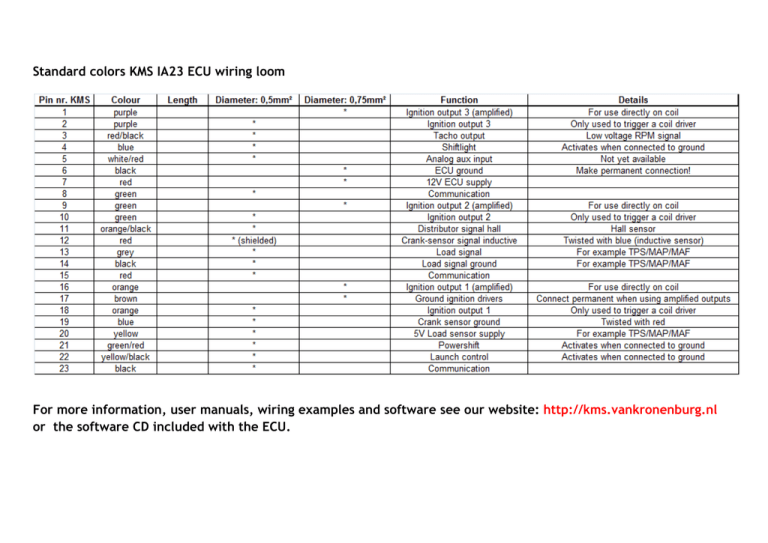
Standard colors KMS IA23 ECU wiring loom For more information, user manuals, wiring examples and software see our website: http://kms.vankronenburg.nl or the software CD included with the ECU. IA23 main wiring Note 1: The IA23 ECU has the possibility to use the Throttle Position Sensor OR MAP sensor as an engine load sensor. Note 2: The IA23 ECU also has the possibility to use either an inductive sensor at the crank, an inductive sensor at the distributor OR a hall effect sensor at the distributor to determine RPM and crank position. Selecting the applied sensor in the software can be done under ‘Options (F4)’ ‘RPM pickup’ ‘Crank type’. Note 3: For wiring of the ignition system, 3 amplified (with internal ignition drivers for direct use on none amplified coils) and 3 none amplified (without internal ignition drivers for direct use on amplified coils) ignition outputs can be used. Connection/wiring of these outputs can be seen in the wiring examples for multiple applications. Note 4: The value/capacity of the fuse is dependent on the total maximum current of the electrical components connected. See wiring examples for deterring the fuse values. Note 5: Preferably put all ground connections (except internal ignition driver (pin 17) and coil grounds!) on the same chassis point, to prevent a difference in potential between the grounds. Warning: The internal ignition driver (pin 17) and coil grounds should be connected to the chassis on a separate point to prevent remaining ignition currents from transferring to the ECU system.
