11) AE Insulation Deterioration Diagnostic System “AE
advertisement

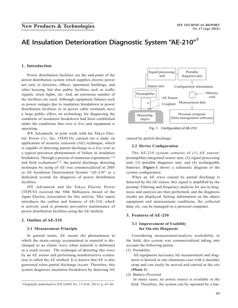
New Products & Technologies JFE TECHNICAL REPORT No. 17 (Apr. 2012) AE Insulation Deterioration Diagnostic System “AE-210”† 1. Introduction Power distribution facilities are the end-point of the power distribution system which supplies electric power not only to factories, offices, apartment buildings, and other housing, but also public facilities such as traffic signals, street lights, etc. And, an enormous number of the facilities are used. Although equipment failures such as power outages due to insulation breakdown in power distribution facilities or in power cable terminals have a large public effect, no technology for diagnosing the condition of insulation breakdown had been established under the conditions that wire is live and equipment is operating. JFE Advantech, in joint work with the Tokyo Electric Power Co., Inc. (TEPCO), carried out a study on application of acoustic emission (AE) technique, which is capable of detecting partial discharge to a live wire as a typical precursor phenomenon of failure in insulation breakdown. Through a process of numerous experiments 1,2) and field evaluations2,3), the partial discharge detecting technique by using of AE was commercialized in 2005 as AE Insulation Deterioration System “AE-210” as a dedicated system for diagnosis of power distribution facilities. JFE Advantech and the Tokyo Electric Power (TEPCO) received the 50th Shibusawa Award of the Japan Electric Association for this activity. This report introduces the outline and features of AE-210, which is actively used to promote preventive maintenance of power distribution facilities using the AE method. 2. Outline of AE-210 2.1 Measurement Principle In general terms, AE means the phenomenon in which the strain energy accumulated in material is discharged as an elastic wave when material is deformed or a crack occurs. The technique of detecting this wave by an AE sensor and performing nondestructive evaluation is called the AE method. It is known that AE is also generated when partial discharge occurs. Therefore, this system diagnoses insulation breakdown by detecting AE † Originally published in JFE GIHO No. 27 (Feb. 2011), p. 65–66 Signal processing unit Sensor unit Preamplifier Portable diagnosis unit Configuration information AE Sensor Memory card Couplant Measurement data Measuring object Personal computer (Data management software) Fig. 1 Configuration of AE-210 caused by partial discharge. 2.2 Device Configuration The AE-210 system consists of (1) AE sensor/ preamplifier-integrated sensor unit, (2) signal processing unit, (3) portable diagnosis unit, and (4) rechargeable batteries. Figure 1 shows a schematic diagram of the system configuration. When an AE wave caused by partial discharge is detected by the AE sensor, this signal is amplified by the preamp. Filtering and frequency analysis for use in diagnosis and analysis are then performed, and the diagnosis results are displayed. Setting information on the object equipment and measurement conditions, the collected data, etc. can be managed on a personal computer. 3. Features of AE-210 3.1 Improvement of Usability for On-site Diagnosis Considering measurement/analysis workability in the field, this system was commercialized taking into account the following points. (1) Portability All equipment necessary for measurement and diagnosis is housed in one aluminum case with a shoulder strap and can easily be moved and carried at the site (Photo 1). (2) Battery-Powered In many cases, no power source is available in the field. Therefore, the system can be operated by a bat49 AE Insulation Deterioration Diagnostic System “AE-210” ③ ① Diagnosis unit Carrying box Sensor unit Photo 1 AE-210 in carrying box tery alone, and can be used without an external power supply for one full day (approximately 8 hours) when the default and spare batteries are used. (3) Improved Sensor Workability Easy attachment of the sensor is important when wearing high voltage insulating gloves and measuring AE in constricted spaces. Therefore, the dimensions and shape were designed based on opinions regarding measurement workability in the field, an integrated sensor unit with the AE sensor and the preamplifier was fabricated. 3.2 Improvement in On-site Diagnosis The correlation between the partial discharge quantity and AE amplitude had been investigated in partial discharge tests1,2) previously. In cased of on-site diagnosis, not visual analysis of the wavelength but judgment by a quantitative index is important. As shown in Fig. 2, clear periodicity can be seen in the AE waveform when partial discharge occurs (synchronized with the power source frequency). AE-210 extracts and displays this periodic component as a diagnosis index by signal processing. Figure 3 shows an example of an analysis screenshot of the diagnosis unit. Area ① displays a graph of the AE intensity at each frequency. The periodic component synchronized to AE-amplitude (V) 0.4 0.3 2 × Power frequency cycle 0.2 0.1 0 0.02 0.04 0.06 Time (s) 0.08 Fig. 2 AE waveform by partial discharge 50 ② Fig. 3 Analysis screenshot of diagnosis unit the power source frequency can be seen. Area ② displays the AE intensity at each frequency in order from the highest intensity, and Area ③ displays the periodic component synchronized to the power source frequency, enabling quantitative evaluation. By focusing on periodicity, AE by partial discharge can be easily distinguished from disturbances. This is a major advantage of AE-210. 3.3 Examples of Application to Detecting Abnormality By detecting abnormality using AE-210, power distribution facilities which was able to prevent from accident include the following 7 equipment and 10 actual components3). · Underground Facility Power supply distribution box: Terminal connection part (Ethylene propylene (EP) rubber) Molded disconnect switch electrode (Epoxy resin) Molded disconnect switch bus (Epoxy resin) Multi-circuit switch: Terminal connection part (EP rubber) Multi-circuit electrode (Epoxy resin) High voltage branching unit: Load break elbow (EP rubber) Ground transformer: Load break elbow (EP rubber) ∙ Overhead Facility Pole transformer: Compact transformer primary fuse holder (Epoxy resin and metal) Overhead connector: Internal insulation cylinder (EP rubber) Overhead arrestor: Internal gap (Porcelain material and metal) 4. Conclusion This report introduced the AE insulation deterioration diagnostic system “AE-210,” which was commerJFE TECHNICAL REPORT No. 17 (Apr. 2012) AE Insulation Deterioration Diagnostic System “AE-210” cialized by integrating measurement and analysis technologies of JFE Advantech based on the field needs of the Tokyo Electric Power (TEPCO). It has been introduced by a large number of users and has received a favorable evaluation as a tool for promoting preventive maintenance. As application/evaluation is to continuing to diversifying power distribution facilities and sites, an expanded range of applications is also expected in the future. degradation diagnosis technique.” Proc. 13th Annual Conf. of Power & Energy Society. IEE of Japan, vol. B, 2002. p. 224– 225. (Japanese). 2) Yauchi, Kiyoharu; Kusaka, Norihiro; Oda, Masahiro. “Application of AE testing (Partial Discharge Detection) to Diagnosis of Electric Facilities Related to Underground Cable.” Electricity Site Technology, vol. 44, no. 512, 2005, p. 41–47. (Japanese). 3) Kusaka, Norihiro; Oda, Masahiro. “Diagnosis techniques of electric power distribution installations by means of acoustic emission.” Proc. of 20th Annual Conf. of Power & Energy Society. IEE of Japan, 2009, p. 41-17–41-18. (Japanese). References For Futher Information, Please Contact: 1) Takeda, Kenjiro; Shibata, Takayuki; Oda, Masahiro. “Field examination of partial discharge detection in EP rubber insulation material by using acoustic emission for developing JFE TECHNICAL REPORT No. 17 (Apr. 2012) Tokyo Head Office, JFE Advantech Phone: (81)3-5825-5577 Fax: (81)3-5825-5591 Website: http://www.jfe-advantech.co.jp/eng/ 51


