OVERVIEW OF HMT330WPA
INSTALLATION INSTRUCTION
HMT330WPA
Warmed Probe Accessory
1
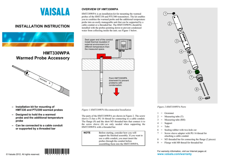
HMT330WPA is an installation kit for mounting the warmed
probes of the HMT330 and PTU300 transmitters. The kit enables
you to combine the warmed probe and the additional temperature
probe into an easily manageable unit that can be supported by a
cable conduit or a threaded bar. The HMT330WPA should be
installed with the probes pointing down to prevent condensed
water from collecting inside the unit; see Figure 1 below.
2
Seal upper end of the conduit.
Install thermal insulation if
external environment is in
different temperature than
the measured space.
3
4
5
6
7
Point HMT330WPA
downward to prevent
problems with
condensation.
8
9
– Installation kit for mounting of
HMT330 and PTU300 warmed probes
– Designed to hold the a warmed
probe and the additional temperature
probe
– Can be connected to a cable conduit
or supported by a threaded bar
Figure 1 HMT330WPA Recommended Installation
The parts of the HMT330WPA are shown in Figure 2. The screw
sleeve (7) has a PG 16 thread for connecting to a cable conduit.
The flange (9) and the short M3 threaded bars that connect it to
the screw sleeve (8) are only needed when supporting the
HMT330WPA with a threaded bar.
NOTE
© Vaisala 2012. All rights reserved.
*M211557EN*
Before starting, consider how you will
support the finished assembly. If you want to
use a cable conduit, you must insert the
probes through the conduit before
assembling them into the HMT330WPA.
Figure 2 HMT330WPA Parts
1
2
3
4
5
6
7
=
=
=
=
=
=
=
Grommet
Measuring tube (T)
Measuring tube (RH)
Support
Tube
Sealing rubber with two-hole cut
Screw sleeve adapter with PG 16 thread for
attaching a cable conduit
8 = M3 threaded bar for connecting the flange (2 pieces)
9 = Flange with M8 thread for threaded bar
For warranty information, visit our Internet pages at:
www.vaisala.com/warranty
ASSEMBLING THE HMT330WPA
1.
Bring the probes together as shown below. Insert the
screw sleeve (7) over the probes and connect them
together with the sealing rubber (6).
2.
Insert the first tube (5) over the probes and tighten it to
the screw sleeve (7). Insert the small white plastic
support (4) to the cable at the base of the RH
measurement probe. Route the cable of the T probe so it
rests in the cutout of the support. Push the screw sleeve
so that the support goes inside the tube.
Visit our Internet pages at
www.vaisala.com
3.
Tighten the RH measuring (3) tube over the warmed
probe. This is the tube with most holes on the sides.
4.
Insert the grommet (1) to the hole at the end of the
T measuring tube (2). Then push the temperature probe
through the grommet and tighten the tube.
MECHANICAL SUPPORT: CABLE CONDUIT
Connect the conduit to the PG 16 thread on the screw sleeve (7).
MECHANICAL SUPPORT: M8 THREADED BAR
To use a threaded bar as a support, first attach the flange (9) to
the screw sleeve (7) using the two M3 threaded bars (8). Use
threadlocking fluid to secure the bars. Then connect your
M8 threaded bar to the flange.
Ref. M211557EN-A


