3D Printed Air Core Inductors for High Frequency Power Converters
advertisement
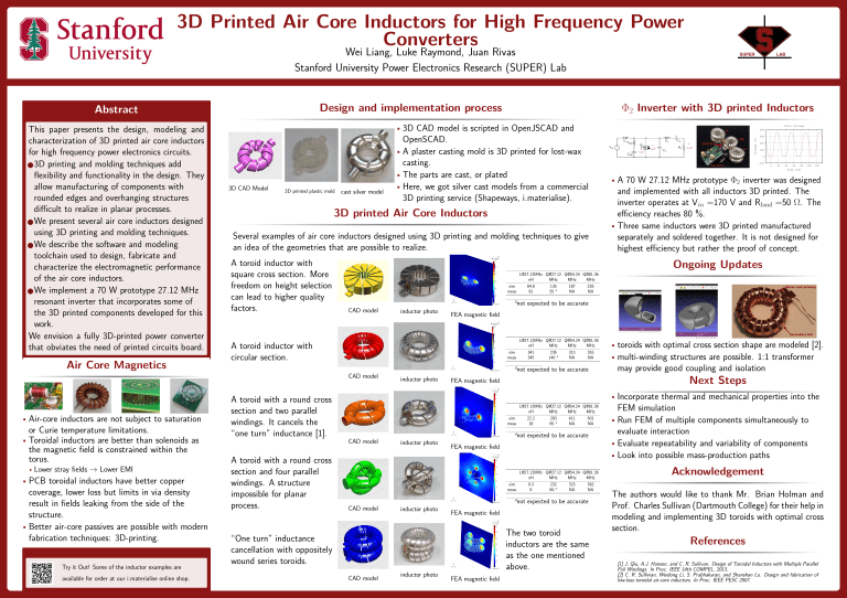
3D Printed Air Core Inductors for High Frequency Power Converters Wei Liang, Luke Raymond, Juan Rivas Stanford University Power Electronics Research (SUPER) Lab Design and implementation process Abstract Air Core Magnetics • 3D CAD model is scripted in OpenJSCAD and 3D CAD Model 3D printed plastic mold cast silver model 3D printed Air Core Inductors Several examples of air core inductors designed using 3D printing and molding techniques to give an idea of the geometries that are possible to realize. A toroid inductor with square cross section. More freedom on height selection can lead to higher quality factors. or Curie temperature limitations. • Toroidal inductors are better than solenoids as the magnetic field is constrained within the torus. a CAD model • Lower stray fields → Lower EMI • PCB toroidal inductors have better copper coverage, lower loss but limits in via density result in fields leaking from the side of the structure. • Better air-core passives are possible with modern fabrication techniques: 3D-printing. Try it Out! Some of the inductor examples are available for order at our i.materialise online shop. inductor photo VIN LMR + − CMR LS Q1 + vgs (t) - + vds (t) - CS + CP RL vload (t) - 200 100 0 -100 0 20 40 60 80 100 120 Time [nS] • A 70 W 27.12 MHz prototype Φ2 inverter was designed and implemented with all inductors 3D printed. The inverter operates at Vin =170 V and Rload =50 Ω. The efficiency reaches 80 %. • Three same inductors were 3D printed manufactured separately and soldered together. It is not designed for highest efficiency but rather the proof of concept. not expected to be accurate FEA magnetic field L@27.12MHz Q@27.12 Q@54.24 Q@81.36 nH MHz MHz MHz sim 341 236 313 355 meas 345 140 a NA NA a A toroid with a round cross section and four parallel windings. A structure impossible for planar process. LF L@27.12MHz Q@27.12 Q@54.24 Q@81.36 nH MHz MHz MHz sim 84.6 135 187 226 a meas 81 55 NA NA A toroid inductor with circular section. A toroid with a round cross section and two parallel windings. It cancels the “one turn” inductance [1]. 300 Ongoing Updates CAD model • Air-core inductors are not subject to saturation OpenSCAD. • A plaster casting mold is 3D printed for lost-wax casting. • The parts are cast, or plated • Here, we got silver cast models from a commercial 3D printing service (Shapeways, i.materialise). Drain Voltage 400 Voltage [V] This paper presents the design, modeling and characterization of 3D printed air core inductors for high frequency power electronics circuits. 1 3D printing and molding techniques add flexibility and functionality in the design. They allow manufacturing of components with rounded edges and overhanging structures difficult to realize in planar processes. 2 We present several air core inductors designed using 3D printing and molding techniques. 3 We describe the software and modeling toolchain used to design, fabricate and characterize the electromagnetic performance of the air core inductors. 4 We implement a 70 W prototype 27.12 MHz resonant inverter that incorporates some of the 3D printed components developed for this work. We envision a fully 3D-printed power converter that obviates the need of printed circuits board. Φ2 Inverter with 3D printed Inductors inductor photo not expected to be accurate • toroids with optimal cross section shape are modeled [2]. • multi-winding structures are possible. 1:1 transformer may provide good coupling and isolation Next Steps FEA magnetic field • Incorporate thermal and mechanical properties into the L@27.12MHz Q@27.12 Q@54.24 Q@81.36 nH MHz MHz MHz sim 22.2 293 411 501 meas 18 65 a NA NA a CAD model inductor photo not expected to be accurate FEA magnetic field L@27.12MHz Q@27.12 Q@54.24 Q@81.36 nH MHz MHz MHz sim 9.3 232 323 392 meas 9 60 a NA NA a CAD model inductor photo FEA magnetic field The two toroid inductors are the same as the one mentioned above. “One turn” inductance cancellation with oppositely wound series toroids. CAD model inductor photo not expected to be accurate FEA magnetic field FEM simulation • Run FEM of multiple components simultaneously to evaluate interaction • Evaluate repeatability and variability of components • Look into possible mass-production paths Acknowledgement The authors would like to thank Mr. Brian Holman and Prof. Charles Sullivan (Dartmouth College) for their help in modeling and implementing 3D toroids with optimal cross section. References [1] J. Qiu, A.J. Hanson, and C. R. Sullivan. Design of Toroidal Inductors with Multiple Parallel Foil Windings. In Proc. IEEE 14th COMPEL, 2013. [2] C. R. Sullivian, Weidong Li, S. Prabhakaran, and Shanshan Lu. Design and fabrication of low-loss toroidal air-core inductors. In Proc. IEEE PESC 2007.

