SERVICE INSTRUCTION
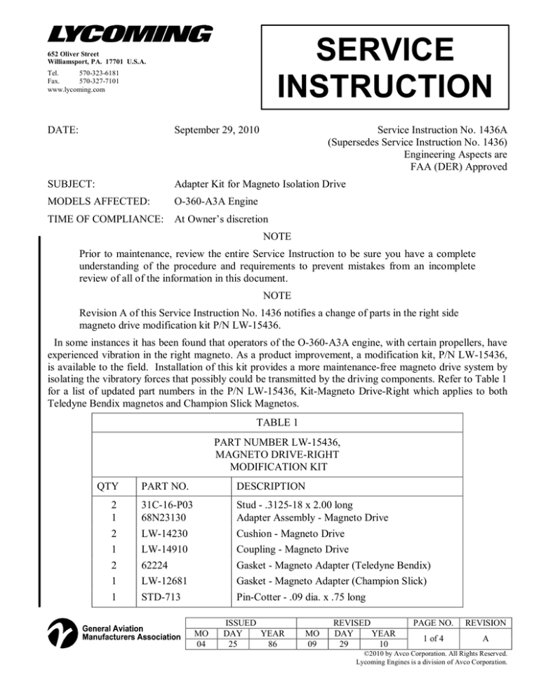
652 Oliver Street Williamsport, PA. 17701 U.S.A. Tel. 570­323­6181 Fax. 570­327­7101 www.lycoming.com DATE: September 29, 2010 Service Instruction No. 1436A (Supersedes Service Instruction No. 1436) Engineering Aspects are FAA (DER) Approved SUBJECT: Adapter Kit for Magneto Isolation Drive MODELS AFFECTED: O­360­A3A Engine TIME OF COMPLIANCE: At Owner’s discretion NOTE Prior to maintenance, review the entire Service Instruction to be sure you have a complete understanding of the procedure and requirements to prevent mistakes from an incomplete review of all of the information in this document. NOTE Revision A of this Service Instruction No. 1436 notifies a change of parts in the right side magneto drive modification kit P/N LW­15436. In some instances it has been found that operators of the O­360­A3A engine, with certain propellers, have experienced vibration in the right magneto. As a product improvement, a modification kit, P/N LW­15436, is available to the field. Installation of this kit provides a more maintenance­free magneto drive system by isolating the vibratory forces that possibly could be transmitted by the driving components. Refer to Table 1 for a list of updated part numbers in the P/N LW­15436, Kit­Magneto Drive­Right which applies to both Teledyne Bendix magnetos and Champion Slick Magnetos. TABLE 1 PART NUMBER LW­15436, MAGNETO DRIVE­RIGHT MODIFICATION KIT QTY 2 1 2 1 2 1 1 PART NO. DESCRIPTION 31C­16­P03 68N23130 LW­14230 LW­14910 62224 LW­12681 STD­713 Stud ­ .3125­18 x 2.00 long Adapter Assembly ­ Magneto Drive Cushion ­ Magneto Drive Coupling ­ Magneto Drive Gasket ­ Magneto Adapter (Teledyne Bendix) Gasket ­ Magneto Adapter (Champion Slick) Pin­Cotter ­ .09 dia. x .75 long MO 04 ISSUED DAY YEAR 25 86 MO 09 REVISED DAY YEAR 29 10 PAGE NO. REVISION 1 of 4 A ©2010 by Avco Corporation. All Rights Reserved. Lycoming Engines is a division of Avco Corporation. As described in the following procedure, this product improvement consists of removing the right magneto, replacing the two studs in the accessory housing and replacing the drive components of the magneto as shown in Figure 1. This procedure applies to both Champion Slick magnetos and Teledyne Bendix magnetos. 1. Remove the right magneto, the two attaching studs, and any gasket material that may remain on the accessory housing (Figure 1). Discard the two attaching studs. 2. From the modification kit, install the two P/N 31C­16­P03 studs in the accessory housing on the magneto mounting pad where shown in Figure 1. The correct driven height of these studs is 1.34 to1.38 in. (34 to 35 mm). 3. Place a new P/N 62224 magneto adapter gasket (from the modification kit) over the two installed studs on the magneto mounting pad of the accessory housing. 4. From the modification kit, install the P/N 68N23130 magneto drive adapter over the studs and install the two P/N LW­14230 magneto drive cushions (from the modification kit) in the magneto drive adapter. 5. Remove the cotter pin, P/N STD­61 nut, P/N STD­143 washer, and drive gear from the magneto drive shaft and the gasket from the magneto flange. Discard the gasket, cotter pin, and drive gear. Keep the nut and washer. 6. Clean the magneto shaft with a cloth dampened with either Methyl­Ethyl Ketone (MEK) or clean unleaded gasoline. Dry thoroughly and apply a light coat of Loctite C5­A® Copper Based Anti­ Seize Lubricant* (or equivalent) to the tapered portion of the magneto shaft. 7. Apply Lubriko** grease (or equivalent) to the mating surface of the magneto flange. 8. Install the P/N LW­14910 magneto drive coupling (from the modification kit) on the magneto shaft. Reassemble using the P/N STD­143 washer and P/N STD­61 nut removed in step 5. Tighten the P/N STD­61 nut to the torque specified in the latest revision of SSP­1776, Table of Limits, and secure the nut with the new P/N STD­713 cotter pin from the modification kit. 9. The modification kit contains two different gaskets, P/N LW­12681 (circular shape) and P/N 62224. The P/N LW­12681 gasket is for Champion Slick magnetos. The remaining gasket, P/N 62224 is for Teledyne Bendix magnetos. Install the new respective magneto gasket on the flange of the magneto, follow Step 9a or Step 9b, depending on the make of the magneto. CAUTION Be sure to install the correct gasket on the corresponding magneto as identified in Figure 1 and instructed below to prevent malfunction and ensure correct clamping pressure to the magneto retainers. a. Refer to Figure 1. On the Teledyne Bendix magneto, from the modification kit, install the new P/N 62224 gasket on the mating surface of the greased (Step 7) magneto flange. b. Refer to Figure 1. On the Champion Slick magneto, from the modification kit, install the new P/N LW­12681 gasket on the mating surface of the greased (Step 7) magneto flange. * Henkel Corporation, Rocky Hill, One Henkel Way, Rocky Hill, CT 06067. ** Lubriko Lubricants, Panef, Inc., 5700 West Douglas Avenue, Milwaukee, WI 53218, Phone (800) 448­1247, International: (414) 464­7200, Fax (414) 462­0980
MO 04 ISSUED DAY YEAR 25 86 MO 09 REVISED DAY YEAR 29 10 PAGE NO. REVISION 2 of 4 A S.I. 1436 10. Time the magneto as described in Section IV of Lycoming’s Direct Drive Overhaul Manual, P/N 60294­7. 11. Install the magneto on the accessory housing. 12. Tighten the magneto attachment nuts to the required torque as listed in the latest revision of SSP­ 1776, Table of Limits. 13. Record compliance with this Service Instruction in the engine logbook for the aircraft.
MO 04 ISSUED DAY YEAR 25 86 MO 09 REVISED DAY YEAR 29 10 PAGE NO. REVISION 3 of 4 A S.I. 1436 Figure 1. Magneto Drive and Component Parts
MO 04 ISSUED DAY YEAR 25 86 MO 09 REVISED DAY YEAR 29 10 PAGE NO. REVISION 4 of 4 A S.I. 1436


