INSTALLATION INSTRUCTIONS
NI-9695 sbRIO Thermal Solution
The National Instruments NI-9695 thermal kit is a heat
spreader accessory used to improve the thermal performance
of the sbRIO-9605/9606/9623/9626/9633/9636.
A 4.5 mm socket driver and a #1 Phillips screwdriver are required to install the
NI-9695.
Note
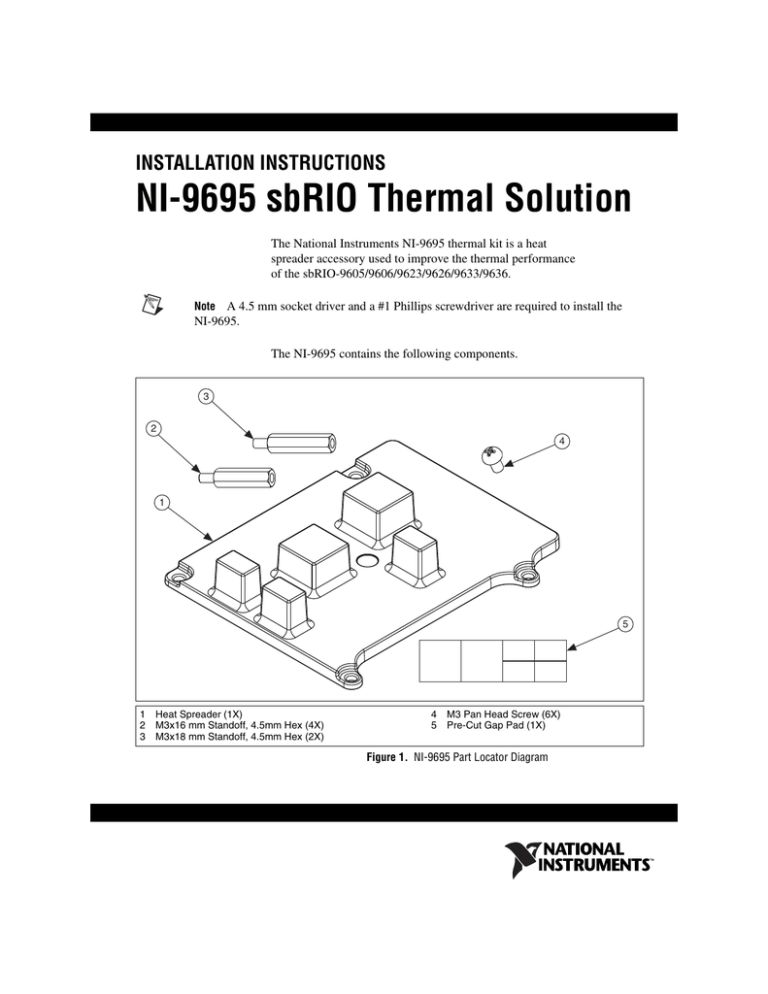
The NI-9695 contains the following components.
3
2
4
1
5
1
2
3
Heat Spreader (1X)
M3x16 mm Standoff, 4.5mm Hex (4X)
M3x18 mm Standoff, 4.5mm Hex (2X)
4
5
M3 Pan Head Screw (6X)
Pre-Cut Gap Pad (1X)
Figure 1. NI-9695 Part Locator Diagram
Mounting and Environmental Considerations
The heat spreader provided in NI-9695 is intended to improve the thermal
performance of sbRIO by removing heat from the components that may
limit the device's maximum operating temperature. The mounting
configuration of the heat spreader can also influence the device's maximum
operating temperature. The spreader can either be mounted with its flat face
against a base mounting surface (ideally a thermally conductive surface) or
with the flat face exposed to air. When the heat spreader's flat face is
exposed to air, a heat sink can potentially be added to the face in order
increase the heat spreader's ability to convect heat to the surrounding
environment. The best orientation will vary by application depending on
factors like the base mounting material, system enclosure material,
interactions with other heat sources in the system, size restraints, and air
flow availability.
For information and examples on environmental and design factors that can
impact the thermal performance of an NI sbRIO system, go to
ni.com/info and enter the Info Code sbriocooling.
Gap Pad
Pre-cut gap pad pieces are provided to act as the thermal interface material
between the heat spreader and sbRIO components. Installing the heat
spreader will require two large gap pad pieces and three small pieces,
making one of the provided small pieces a spare.
Figure 2. Perforated Sections Mark Individual Pieces of Gap Pad
NI 9695 sbRIO Thermal Solution
2
ni.com
The gap pad has clear liners on both sides that must be removed. The
individual pieces of gap pad should be removed from the liners and applied
to the heat spreader prior to assembling the heat spreader to sbRIO. When
applying the gap pad pieces to the heat spreader, the pink side of the gap
pad is to be placed on the heat spreader's raised protrusions, which will
align with sbRIO’s components when fully assembled.
Peel back
Clear Pre-Cut Liner
White Side of Gap Pad
Pink Side of Gap Pad
Clear Un-Cut Liner
Peel back
Figure 3. Side View and Layers of Gap Pad
Figure 4. Gap Pad Placement on Heat Spreader
© National Instruments
3
NI 9695 sbRIO Thermal Solution
Installing the NI 9695
The section provides installation procedures for the following example
configurations.
•
Installing the flat face of the heat spreader to the base mounting surface
•
Installing with the flat face of the heat spreader exposed to air
•
Installing with an RMC
Installing the Flat Face of the Heat Spreader to the Base Mounting
Surface
2
1
1
16 mm standoff
2
18 mm standoff
Figure 5. Heat Spreader to sbRIO: Flat Face Mated to Base Mounting Surface
NI 9695 sbRIO Thermal Solution
4
ni.com
1.
Remove gap pad pieces from both liners and apply pink side to heat
raised protrusions.
2.
Fasten heat spreader to mounting surface using provided 16 mm
standoffs. Tighten completely.
Note Thermal interface material can optionally be used between heat spreader and
mounting surface. Note that thermal interface material may affect system stack height and
levelness.
3.
When mounting the sbRIO-9623/9626/9633/9636, fasten provided
18 mm standoffs to mounting surface in sbRIO footprint holes not
used to fasten the heat spreader. Tighten completely.
4.
Align sbRIO device to standoff holes and fasten using provided
screws. Use caution when aligning the sbRIO device. Once it has been
placed separating the heat spreader and sbRIO device will be difficult
and could potentially damage components.
Caution Do not fasten screws using an automatic screwdriver. Gap pad is a viscoelastic
material and compressing it too fast will potentially break components by placing a large
amount of stress on them. It is recommended to fasten these screws at a rate below
10 in/min.
© National Instruments
5
NI 9695 sbRIO Thermal Solution
Installing With the Flat Face of the Heat Spreader Exposed to Air
1
2
1
16 mm Standoff
2
Not Provided
Figure 6. Heat Spreader to sbRIO: Flat Face Exposed to Air
NI 9695 sbRIO Thermal Solution
1.
Remove gap pad pieces from both liners and apply pink side to heat
spreader pads.
2.
Fasten standoffs (not provided) to mounting surface.
3.
Align sbRIO on standoffs and fasten using provided 16 mm standoffs.
When mounting sbRIO-9623/9626/9633/9636, fasten last two holes
with provided screws. Tighten completely.
4.
Align heat spreader to standoff holes and fasten using provided screws.
Use caution when aligning the heat spreader. Once it has been placed
it should not be considered reworkable.
6
ni.com
Caution Do not fasten screws using an automatic screwdriver. Gap pad is a viscoelastic
material and compressing it too fast will potentially break components by placing a large
amount of stress on them. It is recommended to fasten these screws at a rate below
10 in/min.
Installing With an RMC
An RMC can be used with the heat spreader in either mounting orientation.
However, the standoffs used to separate sbRIO and the RMC are not provided in this kit.
Figure 7 shows one example of an RMC being installed to a sbRIO-9626 with the flat face
of the heat spreader mated to the base mounting surface.
Note
2
3
1
1
16 mm Standoff
2
Not Provided
3
18 mm Standoff
Figure 7. Heat Spreader to sbRIO: With RMC
© National Instruments
7
NI 9695 sbRIO Thermal Solution
1.
Remove gap pad pieces from both liners and apply pink side to heat
spreader pads.
2.
Fasten heat spreader to mounting surface using provided 16 mm
standoffs. Tighten completely.
Thermal interface material can optionally be used between heat spreader and
mounting surface. Note that thermal interface material may affect system stack height and
levelness.
Note
3.
When mounting sbRIO-9623/9626, fasten provided 18 mm standoffs
to mounting surface in sbRIO footprint holes not used to fasten the heat
spreader. Tighten completely.
4.
Align sbRIO device to standoff holes and fasten using standoffs of the
proper height (not provided). See sbRIO manual for information on
selecting the proper standoff height. Use caution when aligning the
sbRIO device. Once it has been placed separating the heat spreader and
sbRIO device will be difficult and could potentially damage
components.
Caution Do not fasten screws using an automatic screwdriver. Gap pad is a viscoelastic
material and compressing it too fast will potentially break components by placing a large
amount of stress on them. It is recommended to fasten these screws at a rate below
10 in/min.
5.
Align RMC to standoff holes and mate RMC connectors. Fasten using
the provided screws.
Specifications
Physical Characteristics
Torque for screws ....................................0.56 N · m
(5 lb · in.)
Weight ....................................................118 g (4.16 oz)
Environmental
Note Systems that use the heat spreader provided in NI 9695 are still required to validate
an sbRIO device per the specifications provided in the sbRIO device manual. Measure the
local ambient temperature by placing thermocouples on both sides of the PCB, 0.2 in.
(5 mm) from the board surface. In addition, the component temperatures should not exceed
their recommended maximum case temperatures. Systems that use the heat spreader
provided in NI-9695 have the option of only measuring the heat spreader temperature in
NI 9695 sbRIO Thermal Solution
8
ni.com
place of measuring the component case temperatures. The heat spreader temperature
should not exceed 85 °C when measured in the designated center depression, which is
shown in Figure 8.
1
2
1
Heat Spreader
2
Center Depression
Figure 8. Heat Spreader Temperature Measurement Location
Note For information and examples on environmental and design factors that can impact
the thermal performance of an NI sbRIO system, go to ni.com/info and enter the Info
Code sbriocooling.
Environmental Management
NI is committed to designing and manufacturing products in an
environmentally responsible manner. NI recognizes that eliminating
certain hazardous substances from our products is beneficial to the
environment and to NI customers.
For additional environmental information, refer to the NI and the
Environment Web page at ni.com/environment. This page contains the
environmental regulations and directives with which NI complies, as well
as other environmental information not included in this document.
© National Instruments
9
NI 9695 sbRIO Thermal Solution
Waste Electrical and Electronic Equipment (WEEE)
EU Customers At the end of the product life cycle, all products must be sent to a WEEE
recycling center. For more information about WEEE recycling centers, National
Instruments WEEE initiatives, and compliance with WEEE Directive 2002/96/EC on
Waste and Electronic Equipment, visit ni.com/environment/weee.
⬉ᄤֵᙃѻક∵ᶧࠊㅵ⧚ࡲ⊩ ˄Ё RoHS˅
Ёᅶ᠋ National Instruments ヺড়Ё⬉ᄤֵᙃѻકЁ䰤ࠊՓ⫼ᶤѯ᳝ᆇ⠽䋼ᣛҸ (RoHS)DŽ
݇Ѣ National Instruments Ё RoHS ড়㾘ᗻֵᙃˈ䇋ⱏᔩ ni.com/environment/rohs_chinaDŽ
(For information about China RoHS compliance, go to ni.com/environment/rohs_china.)
Where to Go for Support
The National Instruments Web site is your complete resource for technical
support. At ni.com/support you have access to everything from
troubleshooting and application development self-help resources to email
and phone assistance from NI Application Engineers.
National Instruments corporate headquarters is located at
11500 North Mopac Expressway, Austin, Texas, 78759-3504.
National Instruments also has offices located around the world to help
address your support needs. For telephone support in the United States,
create your service request at ni.com/support and follow the calling
instructions or dial 512 795 8248. For telephone support outside the United
States, visit the Worldwide Offices section of ni.com/niglobal to access
the branch office Web sites, which provide up-to-date contact information,
support phone numbers, email addresses, and current events.
NI 9695 sbRIO Thermal Solution
10
ni.com
LabVIEW, National Instruments, NI, ni.com, the National Instruments corporate logo, and the Eagle
logo are trademarks of National Instruments Corporation. Refer to the Trademark Information at
ni.com/trademarks for other National Instruments trademarks. Other product and company
names mentioned herein are trademarks or trade names of their respective companies. For patents
covering National Instruments products/technology, refer to the appropriate location: Help»Patents
in your software, the patents.txt file on your media, or the National Instruments Patent Notice
at ni.com/patents. Refer to the Export Compliance Information at ni.com/legal/
export-compliance for the National Instruments global trade compliance policy and how to
obtain relevant HTS codes, ECCNs, and other import/export data.
© 2012 National Instruments. All rights reserved.
373823A-01
Aug12


