14" LX200GPS Superwedge
advertisement

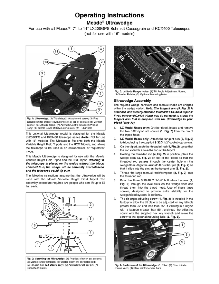
Operating Instructions Meade® Ultrawedge For use with all Meade® 7” to 14” LX200GPS Schmidt-Cassegrain and RCX400 Telescopes (not for use with 16” models) 11 1 4 3 2 2 10 1 9 3 5 6 7 8 Fig. 1: Ultrawedge. (1) Tilt-plate; (2) Attachment screw; (3) Fine latitude control knob; (4) Mounting slot at top of tilt plate; (5) Vernier pointer; (6) Latitude Scale; (7) Azimuth Control Knob; (8) Wedge Body; (9) Bubble Level; (10) Mounting slots; (11) T-bar bolt. This optional Ultrawedge model is designed for the Meade LX200GPS and RCX400 telescope series (Note: Not for use with 16” models). The Ultrawedge fits onto both the Meade Variable Height Field Tripods and the RCX Tripods, and allows the telescope to be used in an astronomical, or “equatorial” mode. This Meade Ultrawedge is designed for use with the Meade Variable Height Field Tripod and the RCX Tripod. Warning: If the telescope is placed on the wedge without the tripod attached to it, the wedge will be seriously overbalanced and the telescope could tip over. The following instructions assume that the Ultrawedge will be used with the Meade Variable Height Field Tripod. The assembly procedure requires two people who can lift up to 55 lbs. each. Fig. 3: Latitude Range Holes. (1) Tilt Angle Adjustment Screw; (2) Vernier Pointer; (3) Optional Mounting Hole. Ultrawedge Assembly The required wedge hardware and manual knobs are shipped within the wedge carton. Note: The tangent arm (5, Fig. 2) is standard and already attached to Meade’s RCX400 tripods; if you have an RCX400 tripod, you do not need to attach the tangent arm that is supplied with the Ultrawedge to your tripod (step #2). 1. 2. 3. 4. 5. 6. 7 7. 2 Meade 3 LX Model Users only: On the tripod, locate and remove the two 8-32 nylon set screws (1, Fig. 2) from the rim of the tripod head. LX Model Users only: Attach the tangent arm (5, Fig. 2) to tripod using the supplied 8-32 X 1/2" socket cap screws. On the tripod, push the threaded rod (4, Fig. 2) up so that the rod extends above the top of the tripod. Holding the threaded rod (4, Fig. 2) in position, place the wedge body (3, Fig. 2) on top of the tripod so that the threaded rod passes through the center hole on the wedge floor. Align the azimuth thrust bar pin (6, Fig. 2) so that it slips into the slot on the tangent arm (5, Fig. 2). Thread the large manual knob/compass (2, Fig. 2) onto the threaded rod. Pass the three 5/16-18 X 1-1/4” buttonhead screws (7, Fig. 2) through the oval slots on the wedge floor and thread them into the tripod head. Use of these three screws, designed to provide extra stability for the wedge/tripod system, is optional. The tilt angle adjusting screw (1, Fig. 3) is installed in the factory to allow the tilt plate to be adjusted for any latitude greater than 25° and less than 55°. If viewing in a region with a latitude greater than 55°, unthread the adjusting screw with the supplied hex key wrench and move the screw to the optional mounting hole (3, Fig. 3). 1 6 4 3 2 5 1 Fig. 2: Mounting the Ultrawedge. (1) Position of nylon set screws; (2) Manual knob/compass; (3) Wedge body; (4) Threaded rod; (5) Tangent arm (LX Users only); (6) Azimuth thrust bar pin; (7) Buttonhead crews. Fig. 4: Back view of the Ultrawedge: (1) T-bar; (2) Fine latitude control knob; (3) Steel reinforcement bars. 2 20° 25° 30° E — Declination — W 40° 50° 60° 50° 40° 30° 25° 24° 22° 21° 20° 19° 18° 17° 16° 15° 14° 13° 12° 11° 10° 9° 8° 7° 6° 3° 5° 4° 2° 1° 23° 22° 21° 20° 19° 18° 17° 16° 15° 14° 13° 12° 11° 10° 9° 8° 7° 6° 5° 4° 3° 2° 1° 0° Fig. 5: Magnetic Declination Map. drive base. Firmly tighten the bolt. Do not overtighten. Mounting the Telescope on the Ultrawedge 1. 2. Thread one of the provided mounting screws into the hole on the underside of the telescope drive base. The desired hole is located at the curved end of the telescope drive base. Grasp the two fork arms of the telescope firmly, with the control panel toward you, place the telescope onto the wedge tilt plate (1, Fig. 1) by sliding the mounting screw on the telescope base into the slot at the top tilt plate (4, Fig.1). 3. Insert the two remaining provided mounting screws through the underside of the tilt plate (10, Fig. 1) and into the underside of the drive base. Firmly tighten the screws. Do not overtighten. 4. Insert the T-bolt (1, Fig. 4) through the center of the underside of the tilt plate and into the underside of the Note: It is important to insert the T-bolt into the wedge-telescope assembly. The T-bolt insures the precise pointing accuracy of the Ultrawedge. The telescope is now fully mounted onto the wedge and tripod. Adjustments in wedge latitude angle and/or azimuth orientation may be made with the telescope in place. Setting the Observing Latitude Look up the latitude of the desired observing site (most road maps show latitude lines). Then, loosen the attachment screws (2, Fig. 1) and rotate the fine latitude control knob (3, Fig. 1) while reading the latitude scale (6, Fig. 1). The latitude pointer is a vernier scale (5, Fig. 1) which will allow the tilt angle to be set to within 0.25°. When the tilt plate is aligned with the desired latitude, tighten the attachment screws. Aligning the Magnetic Compass With the aid of the magnetic compass, a telescope can be polar 3 2 1 1 3 2 N E W W E 4 6 W W N S E 5 S E Fig. 6: Magnetic Compass. (1) 16° West Declination; (2) Point of Knob and “North” Line Up; (3) Declination Scale; (4) Magnetic Pointing Arrow; (5) Manual Knob; (6) Orientating Arrow. aligned in locations where the view of Polaris is obstructed or even before the skies get dark. The compass has an adjustment to compensate for the local angle of Magnetic Declination—the difference between Magnetic North (which the compass shows) and true north (where the telescope should be pointed). Note: Magnetic Declination should not be confused with the astronomical term “Declination” which, when used with “Right Ascension,” describes the celestial coordinate 2 1 N W Fig. 9: Ultrawedge. (1) Magnetic North; (2) Centerline of Wedge, True North. system. 1. Setting Magnetic Declination: In order to obtain an accurate reading using the compass, first adjust the compass to compensate for the Magnetic Declination of the observing location. Determine the Magnetic Declination in the observing area by utilizing the Magnetic Declination Map (Fig. 5). b. Squeeze the clear central disk of the compass between the thumb and index finger of your left hand. c. With the right hand, rotate the outer dial until the orienting arrow (6, Fig. 6) (the black arrow painted on the inside clear surface) is lined up with the desired Magnetic Declination angle on the declination scale (3, Fig. 6). Notice that East Magnetic Declination is to the right of the “North” position and West Magnetic Declination is left of the “North” position. For example, (1, Fig. 6) shows the correct setting for 16° West Declination which covers Providence, Rhode Island. E a. W E S 2. Compass Installation: The Magnetic Compass is now set for the correct Magnetic Declination angle. To attach the compass to the Ultrawedge, follow these steps: Fig. 7: Ultrawedge. (1) Centerline of Wedge; (2) Magnetic North. a. Position the compass into the manual knob so that the 360° location on the direction scale (the “North” position) lines up with one of the nine points of the knob (5, Fig. 6). b. Press the compass firmly into the manual knob. 2 1 3 W W N 3. Finding True North: The Magnetic Compass is now ready to use. Follow these simple steps for a quick and easy azimuth alignment: E Slightly loosen the knob/compass and the three buttonhead screws in the wedge floor to allow for rotation of the Ultrawedge under the knob/compass. The magnetic pointing arrow will point to magnetic north (2, Fig. 7). b. Rotate the knob/compass so that the magnetic pointing arrow lies directly over the painted black orientating arrow (Fig. 8). The “North” position on the direction scale (and the point on the knob/compass) now point directly north. c. Manually rotate the Ultrawedge in azimuth around the threaded rod (without moving the knob/ compass) until the centerline of the wedge is aligned with the point of the S a. E Fig. 8: Ultrawedge. (1) Centerline of Wedge; (2) Magnetic North; (3) True North. 4 knob/compass (Fig. 9). The centerline of the Ultrawedge now falls directly on the true north line. d. Tighten the knob/compass, locking the Ultrawedge into place. The tripod and Ultrawedge are now pointed directly toward celestial north, without ever having seen the North Star. If you have a question concerning use of the Meade ULTRAWEDGE, call the Meade Instruments Customer Service Department at (800) 626-3233. Customer Service hours are 7:00 AM to 6:00 PM, Pacific Time, Monday through Friday. Caution: Due to the weight and size of this product please use extreme caution whenever assembling, disassembling, lifting, transporting or storing this product. Two or more persons should always be used whenever performing any of the above tasks. Disregard for the above warning could result in serious injury or death. Ver. 01.06 14-0216-06


