White Paper
Input Signal Edge Rate Guidance
Introduction
Large and fast PLD designs must have good signal integrity to function properly. Input signal edge rates that are not
well constrained (either too fast or too slow) can degrade signal integrity and even cause functional failures in the
design.
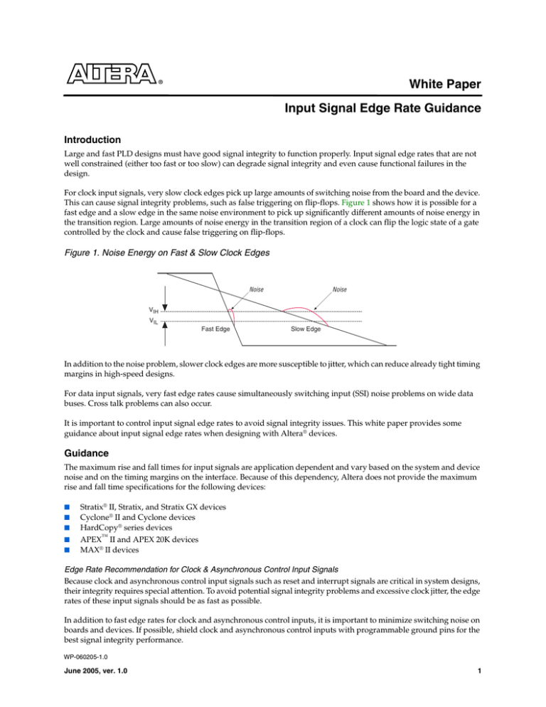
For clock input signals, very slow clock edges pick up large amounts of switching noise from the board and the device.
This can cause signal integrity problems, such as false triggering on flip-flops. Figure 1 shows how it is possible for a
fast edge and a slow edge in the same noise environment to pick up significantly different amounts of noise energy in
the transition region. Large amounts of noise energy in the transition region of a clock can flip the logic state of a gate
controlled by the clock and cause false triggering on flip-flops.
Figure 1. Noise Energy on Fast & Slow Clock Edges
Noise
Noise
VIH
VIL
Fast Edge
Slow Edge
In addition to the noise problem, slower clock edges are more susceptible to jitter, which can reduce already tight timing
margins in high-speed designs.
For data input signals, very fast edge rates cause simultaneously switching input (SSI) noise problems on wide data
buses. Cross talk problems can also occur.
It is important to control input signal edge rates to avoid signal integrity issues. This white paper provides some
guidance about input signal edge rates when designing with Altera® devices.
Guidance
The maximum rise and fall times for input signals are application dependent and vary based on the system and device
noise and on the timing margins on the interface. Because of this dependency, Altera does not provide the maximum
rise and fall time specifications for the following devices:
■
■
■
■
■
Stratix® II, Stratix, and Stratix GX devices
Cyclone® II and Cyclone devices
HardCopy® series devices
APEX™ II and APEX 20K devices
MAX® II devices
Edge Rate Recommendation for Clock & Asynchronous Control Input Signals
Because clock and asynchronous control input signals such as reset and interrupt signals are critical in system designs,
their integrity requires special attention. To avoid potential signal integrity problems and excessive clock jitter, the edge
rates of these input signals should be as fast as possible.
In addition to fast edge rates for clock and asynchronous control inputs, it is important to minimize switching noise on
boards and devices. If possible, shield clock and asynchronous control inputs with programmable ground pins for the
best signal integrity performance.
WP-060205-1.0
June 2005, ver. 1.0
1
Altera Corporation
Input Signal Edge Rate Guidance
Altera’s MAX II devices have built-in Schmitt triggers for each input I/O pin. Schmitt triggers improve noise immunity
on input signals. Altera recommends that designers turn on the Schmitt trigger for input pins with slow input signals.
Edge Rate Recommendation for Data Input Signals
Potential cross talk and simultaneously switching input noise problems can occur in data input signals, especially wide
bus data signals, that have fast signal edges. Altera recommends that the edge rates of the simultaneously switching
inputs be fast, but not exceed the recommended maximum edge rates listed in Table 1.
Table 1. Recommended Maximum Edge Rate
Device
Stratix II
Number of Simultaneously Recommended Maximum
Switching Inputs per Bank Data Input Signal Edge Rate
90
2.0 V/ns
72
3.0 V/ns
90
1.0 V/ns
72
1.5 V/ns
From 64 to 72
0.6 V/ns
From 32 to 36
1.0 V/ns
From 16 to 18
1.5 V/ns
Cyclone
All I/O pins
1.0 V/ns
MAX II
All I/O pins
1.0 V/ns
Stratix and Stratix GX
Cyclone II
For input signals with slower edge rates than recommended, Altera recommends that the designer do the following, if
the feature is available on the device, to avoid noise sensitivity issues:
■
Set programmable ground pins on the adjacent output pins.
■
Turn on slow slew rate on the adjacent output pins.
■
Turn on the Schmitt trigger on the input signal.
1
The numbers shown in Table 1 are recommendations only. A faster edge rate may work fine, depending on
your application. The actual performance of a device in a system is fully system dependent.
Summary
Input signal edge rate requirements are application dependent. Altera recommends using as fast an edge rate as
possible for clock and asynchronous control input signals to avoid potential signal integrity issues. For wide data bus
input signals, Altera recommends that designers set a fast edge rate, but not exceed the maximum edge rates shown in
Table 1.
®
101 Innovation Drive
San Jose, CA 95134
(408) 544-7000
http://www.altera.com
Copyright © 2005 Altera Corporation. All rights reserved. Altera, The Programmable Solutions Company, the stylized Altera logo, specific
device designations, and all other words and logos that are identified as trademarks and/or service marks are, unless noted otherwise, the
trademarks and service marks of Altera Corporation in the U.S. and other countries. All other product or service names are the property of
their respective holders. Altera products are protected under numerous U.S. and foreign patents and pending applications, maskwork rights,
and copyrights. Altera warrants performance of its semiconductor products to current specifications in accordance with Altera's standard
warranty, but reserves the right to make changes to any products and services at any time without notice. Altera assumes no responsibility or
liability arising out of the application or use of any information, product, or service described herein except as expressly agreed to in writing
by Altera Corporation. Altera customers are advised to obtain the latest version of device specifications before relying on any published
information and before placing orders for products or services.
2


