Industrial Data Communication Products
Data Comm.
DCP35
DIN Rail Signal-Powered RS-232 Line Drivers
Description
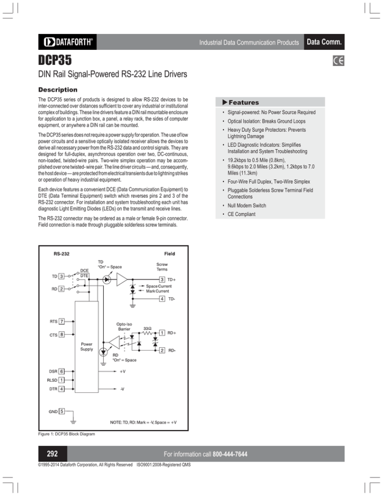
The DCP35 series does not require a power supply for operation. The use of low
power circuits and a sensitive optically isolated receiver allows the devices to
derive all necessary power from the RS-232 data and control signals. They are
designed for full-duplex, asynchronous operation over two, DC-continuous,
non-loaded, twisted-wire pairs. Two-wire simplex operation may be accomplished over one twisted- wire pair. The line driver circuits — and, consequently,
the host device — are protected from electrical transients due to lightning strikes
or operation of heavy industrial equipment.
Each device features a convenient DCE (Data Communication Equipment) to
DTE (Data Terminal Equipment) switch which reverses pins 2 and 3 of the
RS-232 connector. For installation and system troubleshooting each unit has
diagnostic Light Emitting Diodes (LEDs) on the transmit and receive lines.
The RS-232 connector may be ordered as a male or female 9-pin connector.
Field connection is made through pluggable solderless screw terminals.
Features
S
The DCP35 series of products is designed to allow RS-232 devices to be
inter-connected over distances sufficient to cover any industrial or institutional
complex of buildings. These line drivers feature a DIN rail mountable enclosure
for application to a junction box, a panel, a relay rack, the sides of computer
equipment, or anywhere a DIN rail can be mounted.
• Signal-powered: No Power Source Required
• Optical Isolation: Breaks Ground Loops
• Heavy Duty Surge Protectors: Prevents
Lightning Damage
• LED Diagnostic Indicators: Simplifies
Installation and System Troubleshooting
• 19.2kbps to 0.5 Mile (0.8km),
9.6kbps to 2.0 Miles (3.2km), 1.2kbps to 7.0
Miles (11.3km)
• Four-Wire Full Duplex, Two-Wire Simplex
• Pluggable Solderless Screw Terminal Field
Connections
• Null Modem Switch
• CE Compliant
Figure 1: DCP35 Block Diagram
292
For information call 800-444-7644
©1995-2014 Dataforth Corporation, All Rights Reserved ISO9001:2008-Registered QMS
Industrial Data Communication Products
Specifications
Ordering Information
Typical❇ at TA=+25°C
DCP35
Model
Bit Rate (bps)
bps vs Distance
Distance(miles)
Distance(km)
0-19.2kbps
19.2k
9.6k
0.5
2.0
0.8
3.2
Common Mode Isolation
Surge: 500Vp, 1 min.
Continuous: 300Vrms
ANSI/IEEE C37.90.1
Differential Mode Surge Protection
(3 devices)
Modes
4.8k
3.0
4.8
Model
DCP35-P
DCP35-S
2.4k 1.2k-0
5.0 7.0
8.1 11.3
Channel Lines
Control Lines (1)
TD, RD
RTS, CTS, DTR, DSR, RLSD(DCD)
Null Modem Switch
1 (Reverses RS-232 pins 2 and 3)
Power
RS-232 Data
RS-232 Control Signals
RS-232 data and control signals
±5V to ±15V, 3.0mA to 10.0mA
±6V to ±15V, 3.0mA to 10.0mA
Environmental:
Operating Temperature Range
Storage Temperature Range
Relative Humidity
0°C to +70°C
–10°C to +85°C
0 to 95% Noncondensing
Dimensions
4.2” x 3.3” x 0.89”
(107mm x 84mm x 22.5mm)
Weight
4.2 oz (119g)
MTTF
>150,000 hrs
(2)
9-Pin Connector
Termination
1 ch Male
1 ch Female
Screw terminals
Screw terminals
RS-232 Pin Descriptions
Pin 1 RLSD [8] Receive Line Signal
Detect
Pin 2 RD
[3] Receive Data
Pin 3 TD
[2] Transmit Data
Pin 4 DTR [20] Data Terminal Ready
Pin 5 SG
[7] Signal Ground
Pin 6 DSR [6] Data Set Ready
Pin 7 RTS [4] Request To Send
Pin 8 CTS [5] Clear To Send
Asynchronous 4-wire full-duplex, 2-wire simplex
(1)
Data Comm.
Field Pin Descriptions
Screw Terms
Pin 1 RD+ Receive Data +
Pin 2 RD- Receive Data Pin 3 TD+ Transmit Data +
Pin 4 TD- Transmit Data -
Pin numbers given are for the 9-pin connector with the 25-pin
equivalent in [ ].
Figure 2: DCP35 Dimensions
Visit our website www.dataforth.com
293
©1995-2014 Dataforth Corporation, All Rights Reserved ISO9001:2008-Registered QMS
Data Comm
NOTES:
❇
Contact factory or your local Dataforth sales office for maximum values.
(1) TD = Transmit Data, RD = Receive Data, RTS = Request To Send, CTS = Clear To Send, DTR = Data
Terminal Ready, DSR = Data Set Ready, RLSD = Received Line Signal Detect (DCD = Data Carrier Detect).
(2) Ground-benign environmental conditions (no salt atmosphere, <50°C ambient temperature).


