Instruction Sheet
408-10383
Manual Service Disconnect (MSD)
1587992-[ ]
25 AUG 10 Rev A
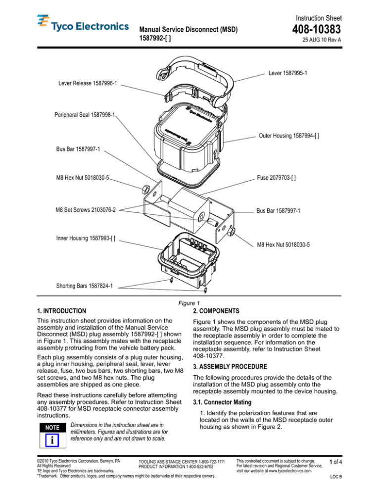
Lever 1587995-1
Lever Release 1587996-1
Peripheral Seal 1587998-1
Outer Housing 1587994-[ ]
Bus Bar 1587997-1
M8 Hex Nut 5018030-5
Fuse 2079703-[ ]
M8 Set Screws 2103076-2
Bus Bar 1587997-1
Inner Housing 1587993-[ ]
M8 Hex Nut 5018030-5
Shorting Bars 1587824-1
Figure 1
1. INTRODUCTION
2. COMPONENTS
This instruction sheet provides information on the
assembly and installation of the Manual Service
Disconnect (MSD) plug assembly 1587992-[ ] shown
in Figure 1. This assembly mates with the receptacle
assembly protruding from the vehicle battery pack.
Figure 1 shows the components of the MSD plug
assembly. The MSD plug assembly must be mated to
the receptacle assembly in order to complete the
installation sequence. For information on the
receptacle assembly, refer to Instruction Sheet
408-10377.
Each plug assembly consists of a plug outer housing,
a plug inner housing, peripheral seal, lever, lever
release, fuse, two bus bars, two shorting bars, two M8
set screws, and two M8 hex nuts. The plug
assemblies are shipped as one piece.
Read these instructions carefully before attempting
any assembly procedures. Refer to Instruction Sheet
408-10377 for MSD receptacle connector assembly
instructions.
NOTE
i
Dimensions in the instruction sheet are in
millimeters. Figures and illustrations are for
reference only and are not drawn to scale.
3. ASSEMBLY PROCEDURE
The following procedures provide the details of the
installation of the MSD plug assembly onto the
receptacle assembly mounted to the device housing.
3.1. Connector Mating
1. Identify the polarization features that are
located on the walls of the MSD receptacle outer
housing as shown in Figure 2.
©2010 Tyco Electronics Corporation, Berwyn, PA
TOOLING ASSISTANCE CENTER 1-800-722-1111
All Rights Reserved
PRODUCT INFORMATION 1-800-522-6752
TE logo and Tyco Electronics are trademarks.
*Trademark. Other products, logos, and company names might be trademarks of their respective owners.
This controlled document is subject to change.
For latest revision and Regional Customer Service,
visit our website at www.tycoelectronics.com
1 of 4
LOC B
408-10383
• Keying options on the MSD plug assembly match
those on the receptacle mounting interface.
• MSD plug assembly and receptacle mounting
interface are correctly oriented (180°).
5. Rotate the lever while maintaining a slight
downward force on the plug assembly, as shown
in Figures 4A and 4B. The lever gear features
will engage the receptacle outer housing and
draw the plug assembly down onto the
receptacle as the lever is rotated.
4A
Polarization Features
Figure 2
2. Line up the polarization features on the MSD
receptacle outer housing with the mating
polarization slots on the plug assembly as
shown in Figure 2.
3. Ensure that the mounting interface surface of
the MSD receptacle wall is clean, and that there
are no surface contaminants within the mounting
footprint.
4. Manually install the MSD plug assembly into
the receptacle mounting interface, making sure
that the polarization features are aligned
correctly as shown in Figures 2 and 3. This is the
pre-staged position, which flexes the passive
latches of the lever release outwards so that the
lever can be released from the pre-stage
position. If the plug assembly and receptacle
mounting interface do not fit together easily,
check the following:
4B
Figure 4
6. Once the lever is rotated to the end of the
travel, an audible “click” will be heard as the
lever latches into position as shown in Figure 5.
Figure 3
Rev A
7. Completed assembly is shown in Figure 6.
2 of 4
408-10383
1
2
Figure 7
Figure 5
Figure 8
Figure 6
2
3.2. Connector Un-Mating
1. Depress the latch firmly. With the latch fully
depressed, rotate the lever upward and away
from the pack as shown in Figure 7.
2. Rotate the lever arm until it stops in the
intermediate position, at approximately 45° from
the pack housing as shown in Figure 8. At this
stage, the high voltage inter-lock connection has
been broken and the circuit is de-energized.
3. Depress the latch firmly. With the latch fully
depressed, rotate the lever upward and away
from the pack as shown in Figure 9.
Rev A
1
Figure 9
3 of 4
408-10383
4. Continue to rotate the lever to the end of
travel (90° from the pack) as shown in Figure 10.
4. CUSTOMER REQUIREMENTS - (WARNINGS AND
DISCLAMERS)
CAUTION Internal components of the MSD are not
serviceable. In the event of part damage or failure,
remove and replace the entire assembly as
!
indicated in this instruction sheet. DO NOT
attempt to separately replace single MSD
components.
5. REPAIR
CAUTION Damaged product should not be used. If a
damaged component is evident, it should be
replaced with a new one.
!
6. REVISION SUMMARY
Initial release of document.
Figure 10
5. Pull straight back on the plug in order to
disengage it from the receptacle as shown in
Figure 11.
Figure 11
Rev A
4 of 4


