Brand Logo
reversed out of
black
IL503004EN
INS #
Installation Instructions - Linear Dimming Control Module
Plenum Rated: 0-10V, 450W/120V, 1000W/277V
Additional Items - As Need
WARNING
Lighting Fixtures must be installed by a qualified electrician.
Junction Boxes
Eaton Lighting Solutions is not responsible if its fixtures are
not installed in accordance with all national and local safety
standards.
Extending Cable
Included in box
Installation Location
Linear Dimming Control Module: 0-10V, 450W/120V,
1000W/277V, Grey Installation Guide
The LDCM-PL is rated to be installed in plenum
spaces. It may also be installed in non-plenum
damp location spaces that comply with NEC.
RoHS
Leader Cable
COMPLIANT
IMPORTANT: Read carefully before installing fixture. Retain for future reference.
Plan the Installation
Verify the Electrical Plan
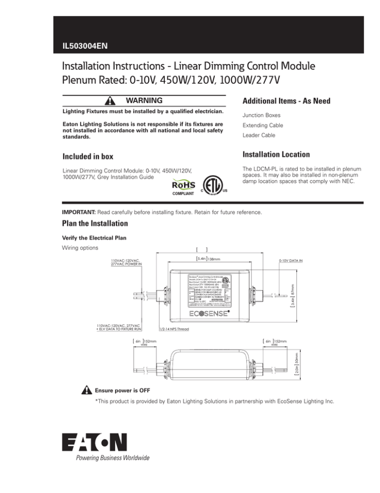
Wiring options
5.4in 138mm
0-10V DATA IN
3.4in 87mm
110VAC-120VAC,
277VAC POWER IN
110VAC-120VAC, 277VAC
+ ELV DATA TO FIXTURE RUN
152mm
WIRE
6in
152mm
WIRE
2.0in 50mm
6in
1/2-14 NPS Thread
Ensure power is OFF
*This product is provided by Eaton Lighting Solutions in partnership with EcoSense Lighting Inc.
Installation Instructions - LDCM - Plenum Rated: 0-10V, 450W/120V, 1000W/277V
Installation Instructions
1. Mounting the LDCM to a J-Box
Mount the power input/output side of the LDCM to the
j-box containing the supply line wires and the fixture load
wires. Use the supplied nut to hold the LDCM in place.
Optionally the Data control wire end of the LDCM can
also be mounted to a j-box.
Note: One (1) LDCM Module is required per maximum
length fixture run
JUNCTION BOX
2. Connect to Power and Data
Connect the input line power to the black(live) and
white(Neutral) input power wires on the LDCM.
Connect the output load wires going to the fixtures to the
red(live) and grey(neutral) output wires on the LDCM.
Connect the input ground building wire to the output
ground going to the fixture. The LDCM does not need to
be grounded.
2
EATON
IL503004EN
Installation Instructions
JUNCTION BOX
Installation Instructions - LDCM - Plenum Rated: 0-10V, 450W/120V, 1000W/277V
0-10VDC and Resistance Dimming
Connect the purple wire to the + side and the grey to the - side of the 0-10V data signal.
Parameters
Minimum
Maximum
Source current out of
0-10V (+) Purple wire
0mA
1mA
Absolute voltage
Range on 0-10V (+)
Purple wire
-20V
20V
-19mA
7mA
Sink current into
0-10V (+) Purple wire
(+) Purple wire
(+) Purple wire
LDCM
LDCM
(-) Grey wire
V
(-) Grey wire
Connec on of LDCM and resistance dimmer
Connec on of LDCM and 0-10V analog
dimming
LDCM NOTE:
The EcoSense LDCM module
takes a 0-10V dimming signal and
fixed line voltage input and converts
it to a ELV dimmed output for up to
1000W @ 277V or 450W @120V.
ELV
LIGHTING LOAD (1)
The LDCM is rated to mount
directly to a junction box in the
plenum space for easy installation.
RED
GREY
HOT
NEUTRAL
LDCM
YELLOW
120V receptacle
circuit
WHITE
BLACK
Sensors
Sensors
Slider
Station
Wallstations
+
+
A/V
Mode
+
Demand
Response
+
Alert
Mode
Time
Clock
Adjustable Skylights
6
5
Blue
Red
4
Integration Controls
Adjustable Skylights
Switchpack
Receptacle
BMS/Out
QuickConnect Cables
Green
Integration Controls
Black
Brown
Dual Technology
Wall Corner
Occupancy/Vacancy Sensor
(OAWC-DT-120W)
OCC-RJ45
(Occupancy Coupler)
3
2
1
Not Used
Occupancy
Occ
Vac (default)
3
4
Energy
Options
0-10V Gain
Adjustment
2
Reset
1
Status
Default 10%
20%
30%
40%
High End
Energy Options DIP Switch
Demand Response
Low End
Red - Load 2 Out
Purple - Load 3 Out
Blue - Load In
Yellow - Load 1 Out
Black - Line In
White/Black - 120V N
White/Orange - 277V N
BLUE - Emergency Power In
(120/277VAC)
Blue - EM Line In
Blue - EM Loads Out
YELLOW
Emergency Power OUT
Black
Daylight sensor
(DSRC-FMOIR)
Model: OCC-RJ45
Occupancy Sensor Coupler
BLUE - Relay In
(120/277VAC)
White
Red
CAUTION: Bonding between conduit connections is not automatic and must be provided as part of the installation.
WHT/ORG or WHT/BLK
Neutral
BLACK - Hot
(120/277VAC)
SPRC-R-20-120
20A Receptacle
Control
0-10V Dimming Outputs
+ + + Dimmer 3
Dimmer 2
Dimmer 1
Dimmer 3
+
-
Dimmer 2
+
-
Dimmer 1
+
-
0-10V Dimming
Button 1: Load (1),(2),(3) ON, Dimmer 1: 100%,
Dimmer 2: 80%, Dimmer 3: 100%
Button 2: Load (1),(2),(3) ON, Dimmer 1: 80%,
Dimmer 2: 20%, Dimmer 3: 100%
Button 3: Load (1),(2),(3) ON, Dimmer 1: 50%,
Dimmer 2: 100%, Dimmer 3: 25%
Button 4: Press and Hold Raises all dimmers
Button 5: Press and Hold Lowers all dimmers
Button 6: All Loads OFF
Violet - Dimmer 1
Gray - Dimmer 1
Scene 1
Zone 1 UP
Scene 2
Zone 1 DN
Scene 3
Zone 2 UP
Raise
Zone 2 DN
Lower
Zone 3 UP
All Off
Zone 3 DN
Button 1: Press and hold increase Zone 1 lighting 5%
Button 2: Press and hold decrease Zone 1 lighting 5%
Button 3: Press and hold increase Zone 2 lighting 5%
Button 4: Press and hold decrease Zone 2 lighting 5%
Button 5: Press and hold increase Zone 3 lighting 5%
Button 6: Press and hold decrease Zone 3 lighting 5%
RC-6TSB-P4-* RC-6TSB-ZAD-*
Scene Station
Office Station
Scenes are programmable within the
Room Controller using the Personal
Remote (HHPR-RC) and new
programming is accessed through
the Scene Wallstations.
*The maximum cable distance between LDCM and Dimmer is 20M (66ft)
EATON
IL503004EN
Installation Instructions
3
Installation Considerations
Operating Voltage/Power Consumption
110VAC-120VAC, 450W (Maximum) 60Hz 277VAC, 1000W (Maximum) 60Hz
Operating Temperature
-4°F to 104°F ( -20°C to 40°C)
Weight
0.99 lbs / 0.45 kg
Dimensions
7” L x 3.4” W x 2” H
(178 mm x 87 mm x 50 mm)
WARNING
••
Read and understand the installation instructions before attempting to install or use the dimmer control module.
••
Only use dimmer control module with voltage for which it is rated. Do not exceed the specified voltage and current input.
••
Do not use dimmer control module if the housing, or power cable are damaged.
••
Dimmer control module have line voltage risk of shock and no user serviceable parts. Do not attempt to open.
••
Do not hot swap. Ensure that power is off before connecting or disconnecting fixtures in the series.
••
Ensure that main power supply is off before installing or wiring a dimmer control module.
••
••
••
••
••
The external flexible cable or cord of this luminaire cannot be replaced; if the cord is damaged, the luminaire shall be
destroyed.
Hazardous live parts shall not be accessible after installation, and it is the installer’s responsibility to ensure that the
installation/connections are in compliance with national and local electrical codes and regulations.
The wire connection method shall be determined by local electrical codes and regulations, typically using either wire nuts
or screw terminal blocks.
Possibly hazardous optical radiation emitted from this product.
This device may not cause harmful interference, and (2) this device must accept any interference received, including
interference that may cause undesired operation.
Eaton
1121 Highway 74 South
Peachtree City, GA 30269
P: 770-486-4800
www.eaton.com/lighting
Canada Sales
5925 McLaughlin Road
Mississauga, Ontario L5R 1B8
P: 905-501-3000
F: 905-501-3172
© 2016 Eaton
All Rights Reserved
Printed in USA
Publication No. IL503004EN
July 20, 2016
Eaton is a registered trademark.
All trademarks are property
of their respective owners.
Product availability, specifications,
and compliances are subject to
change without notice

