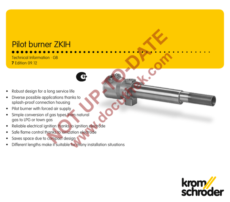
Pilot burner ZKIH
Technical Information · GB
7 Edition 09.12
• Robust design for a long service life
• Diverse possible applications thanks to
splash-proof connection housing
• Pilot burner with forced air supply
• Simple conversion of gas types from natural
gas to LPG or town gas
• Reliable electrical ignition thanks to ignition electrode
• Safe flame control thanks to ionization electrode
• Saves space due to compact design
• Different lengths make it suitable for many installation situations
Contents
Pilot burner ZKIH . . . . . . . . . . . . . . . . . . . . . . . . . . . . . . . . . . 1
Contents . . . . . . . . . . . . . . . . . . . . . . . . . . . . . . . . . . . . . . . . 2
1 Application . . . . . . . . . . . . . . . . . . . . . . . . . . . . . . . . . . . . 3
1.1 Examples of application . . . . . . . . . . . . . . . . . . . . . . . . . 4
1.1.1 On/Off control . . . . . . . . . . . . . . . . . . . . . . . . . . . . . . . . . . . . . 4
1.1.2 Igniting a main burner . . . . . . . . . . . . . . . . . . . . . . . . . . . . . . 4
2 Certification . . . . . . . . . . . . . . . . . . . . . . . . . . . . . . . . . . . . 5
2.1 Approval for Russia . . . . . . . . . . . . . . . . . . . . . . . . . . . . 5
2.2 Declaration of Incorporation pursuant to the
Machinery Directive . . . . . . . . . . . . . . . . . . . . . . . . . . . . . . . 5
3 Function . . . . . . . . . . . . . . . . . . . . . . . . . . . . . . . . . . . . . . . 6
4 Selection . . . . . . . . . . . . . . . . . . . . . . . . . . . . . . . . . . . . . . . 7
4.1 Type code . . . . . . . . . . . . . . . . . . . . . . . . . . . . . . . . . . . . . 7
5 Project planning information . . . . . . . . . . . . . . . . . . . . . . 8
5.1 Installation . . . . . . . . . . . . . . . . . . . . . . . . . . . . . . . . . . . . 8
5.2 Gas/air line connection . . . . . . . . . . . . . . . . . . . . . . . . . 8
6 Technical data . . . . . . . . . . . . . . . . . . . . . . . . . . . . . . . . . . 9
6.1 Dimensions . . . . . . . . . . . . . . . . . . . . . . . . . . . . . . . . . . . 10
6.1.1 ZKIH . . . . . . . . . . . . . . . . . . . . . . . . . . . . . . . . . . . . . . . . . . . . 10
6.1.2 ZKIHB . . . . . . . . . . . . . . . . . . . . . . . . . . . . . . . . . . . . . . . . . . . 11
6.2 Converting units . . . . . . . . . . . . . . . . . . . . . . . . . . . . . . .
7 Maintenance cycles . . . . . . . . . . . . . . . . . . . . . . . . . . . . .
8 Accessories . . . . . . . . . . . . . . . . . . . . . . . . . . . . . . . . . . .
8.1 Ignition transformer . . . . . . . . . . . . . . . . . . . . . . . . . . . .
8.2 Adapter set . . . . . . . . . . . . . . . . . . . . . . . . . . . . . . . . . . .
8.3 Pressure regulators . . . . . . . . . . . . . . . . . . . . . . . . . . . .
Feedback . . . . . . . . . . . . . . . . . . . . . . . . . . . . . . . . . . . . . . .
Contact . . . . . . . . . . . . . . . . . . . . . . . . . . . . . . . . . . . . . . . .
ZKIH · Edition 09.12
12
13
14
14
14
14
15
15
▼
= To be continued
2
1 Application
Flame of the ZKIH during natural gas operation in the open air
Pilot burner ZKIH with splash-proof connection housing
For use as a pilot burner for safe ignition of main burners in
industrial furnaces and firing systems in the iron and steel
industries in the precious, non-ferrous and light metal sector,
as well as in the plastics, fibre and paper industries. Can also
be used as an independently operated burner for applications requiring a burner capacity of 2 to 7 kW (for natural gas
max. 5 kW).
The pilot burner is available in different lengths. It has a splashproof housing. On delivery, the burner is equipped for operation with natural gas. It can easily be converted for operation
with LPG or town gas.
Burner ZKIHB is used for the ignition of high-speed burners.
ZKIH · Edition 09.12
3
Application
1.1 Examples of application
1.1.2 Igniting a main burner
1.1.1 On/Off control
60DJ Z
60DJ Z
VAS
VAS
VAS
VAS
GEH
GEH
ZKIH
GDJ 15L
VR
Main burner
ZKIH
GDJ 15L
LEH
LEH
Install the pilot burner so that reliable ignition of the main
burner is guaranteed.
The gas/air mixture is set using the gas adjusting cock GEH
and the air adjusting cock LEH. For a constant mixture of gas
and air (lambda), one pressure regulator per burner is used
in the gas and air circuits.
ZKIH · Edition 09.12
4
2 Certification
2.1 Approval for Russia
Certified by Gosstandart pursuant to GOST-TR.
Approved by Rostekhnadzor (RTN).
Scan of the approval for Russia (RUS) – see www.docuthek.
com ➔ Elster Kromschröder ➔ Kromschröder, LBE ➔Products
➔ 07 Pilot burners and burners ➔ Pilot burner ZKIH ➔ Kind
of document: Certificate ➔ ZKIH B00050 (nationales Zertifikat
Russland) (RUS)
2.2 Declaration of Incorporation pursuant to the
Machinery Directive
The ZKIH complies with the requirements of EN 746-2 and
the Machinery Directive 2006/42/EC. This is confirmed by the
manufacturer’s Declaration of Incorporation.
ZKIH · Edition 09.12
5
3 Function
Air adjustment
screw
Air
Gas
Ionization
electrode
Burner head
Ignition
electrode
Protective tube + flame tube
= burner tube set
The burner control unit opens the gas and air control valves.
Gas flows through the gas connection and air flows through the
air connection in the burner housing as far as the burner head.
The combustible gas/air mixture is produced downstream
of the burner head. The gas/air mixture is electrically ignited
directly by an ignition electrode. A flame forms which is monitored using an ionization electrode. The air volume required
can be adjusted using the air adjustment screw.
ZKIH · Edition 09.12
6
4 Selection
150
ZKIH
ZKIHB
–
180
–
200
–
230
–
300
–
330
–
400
–
430
–
500
–
530
–
600
–
630
–
700
–
730
–
800
–
830
–
900
–
930 /100
–
R
Order example
ZKIHB 180/100R
4.1 Type code
Code
ZKIH
ZKIHB
150 – 930
/100
R
1)
Description
Pilot burner with forced air supply
For ignition of high-speed burners
Protective tube length1) [mm]
150 to 930
Flame tube length [mm]
100
Rp internal thread
Longer lengths on request.
ZKIH · Edition 09.12
7
5 Project planning information
5.1 Installation
Install and insulate the pilot burner in order to avoid any overheating of the components during operation. Where applicable,
purging air must be used to prevent ingress of aggressive
gases and thermal overload of components.
When a pilot burner is installed in a burner quarl, the burner
tube set can be subjected to very high thermal stress. A means
of cooling the pilot burner must always be provided. Air must
constantly be passed through a 3 mm gap on the outside of
the protective tube. As a result of this measure, the service life
of the pilot burner can be significantly increased.
Protective tube temp. Flame tube temp.
< 500°C (932°F)
≤ 1000°C (1832°F)
The tip of the pilot burner flame tube must not come into contact
with the main burner flame. Safe ignition of the main burner
must be ensured.
When the pilot burner is switched off, the pilot burner air should
continue to flow to ensure that the pilot burner is cooled.
5.2 Gas/air line connection
A gas test point and an air test point must be provided by the
customer upstream of the ZKIH to measure the gas and air
pressure respectively.
ZKIH · Edition 09.12
8
6 Technical data
Burner
ZKIH
with natural gas
kW
2 – 7
max. 5
Capacity
1000 BTU/h
7.6 – 26
max. 17
Gas types: natural gas, LPG (gaseous) and coke oven gas.
Gas inlet pressure: 5 to approx. 50 mbar (2 to approx.
20 "WC),
air inlet pressure: 5 to approx. 30 mbar (2 to approx.
12 "WC),
each depending on the gas type
(burner pressures – see www.docuthek.com,
Kind of document: Operating characteristic diagram).
On delivery: natural gas setting (gas and air pressures:
20 mbar (8 "WC)).
For cold air only.
Flame control: with ionization electrode.
Ignition: direct spark ignition (5 kV ignition transformer).
Housing: aluminium.
Protective tube: stainless steel.
Flame tube: heat-resistant steel.
Max. temperature at the tip of the flame tube:
< 1000°C (< 1832°F),
< 900°C (< 1652°F) for lambda < 1.
Max. temperature of the protective tube: 500°C (932°F).
Gas and air pressures:
see burner diagram at www.docuthek.com,
Kind of document: Operating characteristic diagram.
Flame length at rated capacity: approx. 25 cm (9.8").
Control: On/Off.
ZKIH · Edition 09.12
9
Technical data
6.1 Dimensions
Rp ½"
L1
∅ 52 mm 30 mm
(2.05") (1.18")
∅ 64 mm
(2.52")
72 mm
(2.83")
M6
PG 9
100 mm
(3.94")
∅
29 mm
(1.14")
∅
40 mm
(1.57")
Rp ¼"
85 mm
(3.35")
95 mm
(3.74")
6.1.1 ZKIH
Type
ZKIH 150/100R
ZKIH 200/100R
ZKIH 300/100R
ZKIH 400/100R
ZKIH 500/100R
ZKIH 600/100R
ZKIH 700/100R
ZKIH 800/100R
ZKIH 900/100R
ZKIH · Edition 09.12
Dimensions L1
[mm]
150
200
300
400
500
600
700
800
900
[inch]
5.91
7.87
11.8
15.7
19.7
23.6
27.6
31.5
35.4
10
Technical data > Dimensions
6.1.2 ZKIHB
Rp ½"
L1
∅
52 mm 30 mm
(2.05") (1.18")
∅
64 mm
(2.52")
72 mm
(2.83")
M6
PG 9
ZKIHB 180/100R
ZKIHB 230/100R
ZKIHB 330/100R
ZKIHB 430/100R
ZKIHB 530/100R
ZKIHB 630/100R
ZKIHB 730/100R
ZKIHB 830/100R
ZKIHB 930/100R
ZKIH · Edition 09.12
∅
∅
25 mm 40 mm
(0.98") (1.57")
Rp ¼"
85 mm
(3.35")
95 mm
(3.74")
Type
100 mm
(3.94")
Dimensions L1
[mm]
180
230
330
430
530
630
730
830
930
[inch]
7.09
9.06
13.0
16.9
20.9
24.8
28.7
32.7
36.6
11
Technical data
6.2 Converting units
SI unit ×
m3/h
mbar
mbar
mm
kg
litres
m/s
multiplier = US unit
35.31
CFH
0.0145
psi
0.39
"WC
0.039
inch
2.2
lbs
0.26
gal
ft/s
3.28
ZKIH · Edition 09.12
US unit ×
CFH
psi
"WC
inch
lbs
gal
ft/s
multiplier =
0.0283
68.89
2.54
25.4
0.45
3.79
0.3048
SI unit
m3/h
mbar
mbar
mm
kg
litres
m/s
°C = (°F - 32) × 5/9
°F = (°C × 9/5) + 32
12
7 Maintenance cycles
Twice per year, but if the media are highly contaminated, this
interval should be reduced.
ZKIH · Edition 09.12
13
8 Accessories
8.3 Pressure regulators
8.1 Ignition transformer
For a constant mixture of gas and air (lambda), we recommend
using one pressure regulator 60DJ Z in the gas circuit and
one pressure regulator GDJ 15L in the air circuit per burner.
To ensure safe ignition, we recommend using ignition transformer TGI 5-15/100W or TZI 5-15/100W.
TGI 5-15/100W
60DJ Z, DN 8
TZI 5-15/100W
8.2 Adapter set
For connecting the pilot burner ZKIH to pilot gas and air lines.
Comprising one adapter with 1/4-18 NPT internal thread and
one adapter with 1/2-14 NPT internal thread.
Order No. 74923430
ZKIH · Edition 09.12
GDJ 15L, DN 15
14
Feedback
Finally, we are offering you the opportunity to assess this “Technical Information (TI)” and to give us your opinion, so that we
can improve our documents further and suit them to your needs.
Clarity
Found information quickly
Searched for a long time
Didn’t find information
What is missing? sc sacascsd
No answer
Comprehension
Coherent
Too complicated
No answer
Scope
Too little
Sufficient
Too wide
No answer
Use
To get to know the product
✔ To choose a product
Planning
To look for information
Navigation
I can find my way around
I got “lost”
No answer
My scope of functions
Technical department
Sales
No answer
Remarks
sdvsdvsdvsdv
Kromschröder AG
Michael Rehkamp
m.rehkamp@kromschroeder.com
Osnabrück
(Adobe Reader 7 or higher required)
www.adobe.com
Contact
ZKIH · Edition 09.12
The current addresses of our international agents are
available on the Internet:
www.kromschroeder.de/index.php?id=718&L=1
We reserve the right to make technical modifications
in the interests of progress.
Copyright © 2013 Elster GmbH
All rights reserved.
03251279
Elster GmbH
Postfach 2809 · 49018 Osnabrück
Strotheweg 1 · 49504 Lotte (Büren)
Germany
T +49 541 1214-0
F +49 541 1214-370
info@kromschroeder.com
www.kromschroeder.com
15


