Analog and Digital Fluorescent Lighting Dimming Systems
advertisement
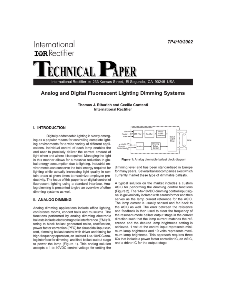
TP4/10/2002 International Rectifier • 233 Kansas Street, El Segundo, CA 90245 USA Analog and Digital Fluorescent Lighting Dimming Systems Thomas J. Ribarich and Cecilia Contenti International Rectifier I. INTRODUCTION Digitally addressable lighting is slowly emerging as a popular means for controlling complete lighting environments for a wide variety of different applications. Individual control of each lamp enables the end user to precisely deliver the correct amount of light when and where it is required. Managing the light in this manner allows for a massive reduction in global energy consumption due to lighting. Industrial environments can conserve the total energy required for lighting while actually increasing light quality in certain areas at given times to maximize employee productivity. The focus of this paper is on digital control of fluorescent lighting using a standard interface. Analog dimming is presented to give an overview of other dimming systems as well. II. ANALOG DIMMING Analog dimming applications include office lighting, conference rooms, concert halls and museums. The functions performed by analog dimming electronic ballasts include electromagnetic interference (EMI) filtering to block ballast generated noise, rectification, power factor correction (PFC) for sinusoidal input current, dimming ballast control with driver and timing for high-frequency operation, an isolated 1-to-10VDC analog interface for dimming, and final ballast output stage to power the lamp (Figure 1). This analog solution accepts a 1-to-10VDC control voltage for setting the Analog Dimmable Electronic Ballast Line Neutral Earth 1 to 10VDC (+) Dimming Control Input (-) EMI Filter Isolation Rectifier Power Factor Correction Ballast Output Stage Lamp Dimming Ballast Control Figure 1: Analog dimmable ballast block diagram dimming level and has been standardized in Europe for many years. Several ballast companies exist which currently market these type of dimmable ballasts. A typical solution on the market includes a custom ASIC for performing the dimming control functions (Figure 2). The 1-to-10VDC dimming control input signal is galvanically isolated with a transformer and then serves as the lamp current reference for the ASIC. The lamp current is usually sensed and fed back to the ASIC as well. The error between the reference and feedback is then used to steer the frequency of the resonant-mode ballast output stage in the correct direction such that the lamp current matches the reference and the desired lamp brightness setting is achieved. 1 volt at the control input represents minimum lamp brightness and 10 volts represents maximum lamp brightness. This approach requires three ICs that include a power factor controller IC, an ASIC, and a driver IC for the output stage TP-A&D Dimming Analog Dimmable Electronic Ballast Line Neutral Earth 1 to 10VDC(+) Dimming Control Input(-) EMI Filter Power Factor Correction Rectifier Transformer Line Neutral Earth Ballast Output Stage Lamp User Control Input Dimming Control Analog Dimmable Electronic Ballast Lamp Analog Dimmable Electronic Ballast Lamp Analog Dimmable Electronic Ballast Lamp Analog Dimmable Electronic Ballast Lamp 1 to 10VDC High/Low Side Driver ASIC Figure 2, Typical analog dimming ASIC solution A standard approach exists on the market which uses the IR2159 Dimming Ballast IC (Figure 3). In this solution, the number of ICs is reduced to two as the dimming control and driver circuitry for the output stage are combined in a single IC Analog Dimmable Electronic Ballast Line Neutral Earth (+) 1 to 10VDC Dimming Control Input(-) EMI Filter Rectifier Transformer Power Factor Correction Ballast Output Stage Lamp IR2159 Figure 3, Analog dimming solution using the IR2159 Dimming IC A complete 1-to-10VDC dimming system includes several analog dimming ballasts connected in parallel and controlled simultaneously from a single dimming control unit (Figure 4). This type of configuration is used in, for example, conference rooms where it is convenient to dim the entire room up or down from a single wall-mounted control unit. 2 Figure 4, Typical 1-10V dimming system Higher-end dimming systems also exist which provide constant light throughout the day. In these type of systems, the lamp brightness is measured in different locations of a large room and converted into a voltage using photocells (Figure 5). This voltage is then fed back to a control unit and compared against a pre-set reference. The resulting error between the two is then used to adjust the 1-to-10VDC input of each dimming ballast such that a constant brightness is maintained. TP-A&D Dimming In applications where there is a mixture of external light and fluorescent lighting, the system will self-dim up or down continuously throughout the day to keep the brightness constant. This is a useful feature in environments such as an office with windows or a museum with skylights. If the sun goes behind a cloud, for example, then the system will dim the lamps up to maintain constant light in the room. Also, to compensate for higher levels of external light near the windows, more light will be generated from the lamps which are located further away from the windows such that the light gradient across a given room is constant. Input Power 1-to-10VDC Control Voltage Photocell Voltage Feedback Dimming Ballast Dimming Ballast Dimming Ballast Dimming Ballast Lamp Lamp Lamp Lamp Room Brightness Measurement Control Unit User Reference Setting Digital Dimmable Electronic Ballast Line Neutral EMI Filter Rectifier Earth Digital Control Input Isolation MicroController Power Factor Correction Ballast Output Stage Lamp Ballast Control Figure 6, Digital dimming ballast block diagram A typical digital dimming solution includes an ASIC for sending and receiving instructions from the microcontroller and an optocoupler for isolating the control input (Figure 7). The ASIC contains the necessary functions for controlling the lamp brightness as well as a digital interface for communicating with the micro-controller. This approach requires four primary ICs which include a power factor controller IC, a microcontroller IC, an ASIC and a driver IC for the output stage Typical Room Digital Dimmable Electronic Ballast Figure 5, Self-dimming constant-light system Line Neutral EMI Filter Power Factor Correction Rectifier Earth III DIGITAL DIMMING A digital dimming ballast includes an EMI filter, rectifier, power factor correction and ballast output stage (Figure 6). The digital ballast also includes a microcontroller for sending and receiving information digitally. The micro-controller functions include storing the ballast address, receiving user instructions, setting the dim reference for the ballast control, receiving status information from the ballast control and sending status information back to the user. This allows for complete and precise control of an entire lighting environment Digital Control Input OptoIsolator MicroController ASIC Ballast Output Stage Lamp High/Low Side Driver Figure 7, Typical digital dimming ASIC solution A standard solution also exists that includes the IR2159 Dimming IC (Figure 8). With this approach the total number of ICs has been reduced to three as the IR2159 also includes the driver circuitry for the ballast output stage. 3 TP-A&D Dimming IV. THE DALI Digital Dimmable Electronic Ballast Line Neutral EMI Filter Rectifier Earth Digital Control Input OptoIsolator MicroController Power Factor Correction Ballast Output Stage Lamp IR2159 Figure 8, Digital dimming solution using the IR2159 dimming IC A complete digital dimming system includes the dimming ballasts and a digital control unit for converting information from an Ethernet connection to the communication protocol required by the micro-controller of each ballast (Figure 9). Applications for this system include building management or studio lighting where it is desired to control single or groups of lamps for conserving energy, performing lamp maintenance or creating precision lighting effects Line Neutral Earth Ethernet FORWARD MESSAGE 1 Start bit 8 Address bits 0 Net-to-DALI Converter 1 0 0 0 2 Stop bits 8 Data bits 0 0 1 0 0 0 0 0 0 0 0 BACKWARD MESSAGE 1 Start bit 8 Data bits 0 1 0 0 2 Stop bits 0 0 0 1 Figure 10, DALI protocol bitstream definition 64 Digital Dimming Ballasts Net-to-DALI Converter 64 Digital Dimming Ballasts Net-to-DALI Converter 64 Digital Dimming Ballasts Figure 9, Typical digital dimming system 4 A system known as the Digitally Addressable Lighting Interface (DALI), an addition to the existing electronic ballast performance Standard IEC929, exists in Europe which has been widely adopted by several companies and is in the process of becoming a standard. This is a two-wire system with a defined digital communication protocol for sending and receiving instructions. The DALI includes a bitstream definition for both a forward and backward going messages (Figure 10). The forward message includes a start bit, 8 address bits, 8 data bits and 2 stop bits. The 8 address bits allows for communication with all of the ballasts at once, groups of ballasts (16 maximum) or individual ballasts (64 maximum). The functions performed by the 8 data bits of the forward or backward message have been summarized in a table (Table 1), and include such features as on/off, dim level and fade time. TP-A&D Dimming Set or Query Actual Dim Level Power On Level System Failure Level Minimum Level Maximum Level Fade Rate Fade Time Change Address Change Group Scene Light Level Physical Minimum Level Status Power Commands Turn On Turn Off Dim Up Dim Down Step Up Step Down Recall Max Recall Min Go To Scene Table 1, DALI data bits functions summary The DALI provides 256 levels of brightness between the minimum and maximum dim levels and also includes a logarithmic dimming curve (Figure 11). This gives larger increments in brightness at high dim levels and smaller increments at low dim levels. The result is a dimming curve which appears more linear to the human eye. V. SOFTWARE-CONTROLLABLE LIGHT A fully-functional digitally addressable dimming ballast was designed, built and tested for performance. The input stage was designed for high power factor and low harmonic distortion using a generic PFC IC. The IR2159 Dimming Ballast IC was used to provide smooth dimming control of the lamp. The IR2159 also includes a 0-to-5V analog dimming input which is convenient for interfacing to a micro-controller. The Microchip Technology PIC16F628 micro-controller was used for the digital control section. The PIC16F628 acts as an interface between the IR2159 ballast controller and the DALI. Data is transmitted to the ballast from the DALI and the PIC16F628 collects the data through an isolation circuit. The PIC16F628 then interprets the data and sends the appropriate signals to the IR2159 if necessary or sends information back to the DALI. The PIC16F628 also performs lamp fault detection and disables the IR2159 if a lamp fault is present. EMI Filter Rectifier PFC PC Micro 1 RA2 RA1 18 2 RA3 RA0 17 RS232-toDALI converter OptoIsolation RA7 16 4 RA5 RA6 15 5 VSS VDD 14 6 RB0 RB7 13 7 RA4 RB6 12 8 RB2 RB5 11 9 RB3 RB4 10 RB1 light level Fade time Fade rate On/Off Fault condition actual level light status ballast Ballast Control 1 VDC HO 16 2 VCO VS 15 3 CPH VB 14 4 DIM VCC 13 5 MAX CO M 12 6 MIN 7 8 IR2159 3 Serial Port PIC16F62 255 Dim Value Output Stage Line Input FMI N IPH LO 11 CS 10 SD 9 Half Bridge Driver Lamp Dimming Feedback Preheat Feedback Lamp Fault Figure 12, IRPLDIM2 digitally addressable dimming ballast 0 1 Lamp Brightness [%] 100 Figure 11, DALI logarithmic dimming curve with 256 brightness levels Software was written for controlling the ballast from a PC. The software has a graphical user interface for performing all of the DALI functions (Figure 13). The PC sends commands via a serial cable to a RS232to-DALI converter which then communicates with the ballast via a two-wire connection. 5 TP-A&D Dimming Figure 13, Graphical user interface of the digital dimming software The ballast and software system successfully performed all DALI functions while giving high-performance dimming as well. Temperature, lifetime, performance margins, packaging, layout, manufacturability and cost were all considered during the design process. VI. CONCLUSIONS An overview has been presented covering both analog and digital dimming systems. An existing digital interface has been used as an example of what functions are possible with a complete digital system. A DALI-compatible reference design has also been shown which allows for complete software control of a fluorescent lamp. IR WORLD HEADQUARTERS: 233 Kansas St., El Segundo, California 90245 Tel: (310) 252-7105 Data and specifications subject to change without notice. 4/10/2002 6

