Another Look at Guy Wire Interactions
advertisement

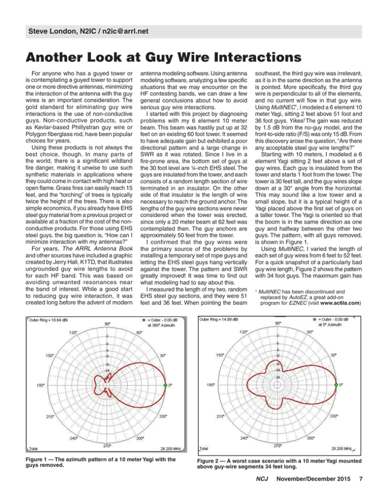
Steve London, N2IC / n2ic@arrl.net Another Look at Guy Wire Interactions For anyone who has a guyed tower or is contemplating a guyed tower to support one or more directive antennas, minimizing the interaction of the antenna with the guy wires is an important consideration. The gold standard for eliminating guy wire interactions is the use of non-conductive guys. Non-conductive products, such as Kevlar-based Phillystran guy wire or Polygon fiberglass rod, have been popular choices for years. Using these products is not always the best choice, though. In many parts of the world, there is a significant wildland fire danger, making it unwise to use such synthetic materials in applications where they could come in contact with high heat or open flame. Grass fires can easily reach 15 feet, and the “torching” of trees is typically twice the height of the trees. There is also simple economics, if you already have EHS steel guy material from a previous project or available at a fraction of the cost of the nonconductive products. For those using EHS steel guys, the big question is, “How can I minimize interaction with my antennas?” For years, The ARRL Antenna Book and other sources have included a graphic created by Jerry Hall, K1TD, that illustrates ungrounded guy wire lengths to avoid for each HF band. This was based on avoiding unwanted resonances near the band of interest. While a good start to reducing guy wire interaction, it was created long before the advent of modern antenna modeling software. Using antenna modeling software, analyzing a few specific situations that we may encounter on the HF contesting bands, we can draw a few general conclusions about how to avoid serious guy wire interactions. I started with this project by diagnosing problems with my 6 element 10 meter beam. This beam was hastily put up at 32 feet on an existing 60 foot tower. It seemed to have adequate gain but exhibited a poor directional pattern and a large change in SWR as it was rotated. Since I live in a fire-prone area, the bottom set of guys at the 30 foot level are ¼-inch EHS steel. The guys are insulated from the tower, and each consists of a random length section of wire terminated in an insulator. On the other side of that insulator is the length of wire necessary to reach the ground anchor. The lengths of the guy wire sections were never considered when the tower was erected, since only a 20 meter beam at 62 feet was contemplated then. The guy anchors are approximately 50 feet from the tower. I confirmed that the guy wires were the primary source of the problems by installing a temporary set of rope guys and letting the EHS steel guys hang vertically against the tower. The pattern and SWR greatly improved! It was time to find out what modeling had to say about this. I measured the length of my two, random EHS steel guy sections, and they were 51 feet and 36 feet. When pointing the beam Figure 1 — The azimuth pattern of a 10 meter Yagi with the guys removed. southeast, the third guy wire was irrelevant, as it is in the same direction as the antenna is pointed. More specifically, the third guy wire is perpendicular to all of the elements, and no current will flow in that guy wire. Using MultiNEC1, I modeled a 6 element 10 meter Yagi, sitting 2 feet above 51 foot and 36 foot guys. Yikes! The gain was reduced by 1.5 dB from the no-guy model, and the front-to-side ratio (F/S) was only 15 dB. From this discovery arose the question, “Are there any acceptable steel guy wire lengths?” Starting with 10 meters, I modeled a 6 element Yagi sitting 2 feet above a set of guy wires. Each guy is insulated from the tower and starts 1 foot from the tower. The tower is 30 feet tall, and the guy wires slope down at a 30° angle from the horizontal. This may sound like a low tower and a small slope, but it is a typical height of a Yagi placed above the first set of guys on a taller tower. The Yagi is oriented so that the boom is in the same direction as one guy and halfway between the other two guys. The pattern, with all guys removed, is shown in Figure 1. Using MultiNEC, I varied the length of each set of guy wires from 6 feet to 52 feet. For a quick snapshot of a particularly bad guy wire length, Figure 2 shows the pattern with 34 foot guys. The maximum gain has 1 MultiNEC has been discontinued and replaced by AutoEZ, a great add-on program for EZNEC (visit www.ac6la.com) Figure 2 — A worst case scenario with a 10 meter Yagi mounted above guy-wire segments 34 feet long. NCJ November/December 2015 7 Figure 3 — Maximum forward gain for a 10 meter Yagi (vertical axis) plotted against different lengths of metallic guy wire (horizontal axis). Figure 6 — Front-to-rear ratio versus guy wire lengths for 15 meter Yagi. Figure 4 — Front-to-rear ratios for the test 10 meter Yagi mounted above different lengths of metallic guys. Figure 7 — Forward gain versus guy wire length for a 4 element 20 meter Yagi. Figure 5 — Forward gain versus guy lengths for a 15 meter Yagi above metallic guys. Figure 8 — Front-to-rear ratio versus guy wire length for a 4 element 20 meter Yagi. dropped by 1.75 dB, and the directivity is much worse. If you examine the impact of the full range of guy wire lengths on gain (see Figure 3) and front-to-rear (F/R) ratio (see Figure 4) you can see that multiples of approximately 0.5 l are particularly bad. This is the expected result; you are putting a resonant parasitic element in the near field of the antenna. Choose a length near a resonant point, and you have severely degraded the performance of the antenna. But even non-resonant guy wires have a penalty associated with them, because there is still some current 8 November/December 2015 NCJ flowing in non-resonant, nearby wires. For example, a non-resonant 43 foot guy wire reduces the gain by about 0.2 dB, and the F/R by about 1 dB. That might be an acceptable performance loss. On 15 meters, the story is about the same. I modeled a 5 element Yagi sitting above the guy wires. The relationship between guy wire lengths on gain and on F/R may be seen in Figures 5 and 6, respectively, showing some lengths to clearly avoid. Again, choosing guy wire lengths near resonance (near 22 and 45 feet) is undesirable, with a drop in forward gain of 2.5 dB and 1.5 dB, but even nonresonant guys cause some degradation. For 20 meters, I used a 4 element Yagi in the model. Compared to 10 and 15 meters, the effects of choosing a length near resonance (about 34 feet) are even more pronounced, with a gain degradation of almost 4 dB. As the number of elements in the antenna drops, a greater percentage of the antenna currents flow in the parasitic (and destructive!) guy wires (see Figures 7 and 8). A comparison of the 4 element Yagi with and without 34 foot guy wires (see Figure 9) demonstrates the kind of pattern degradation you certainly want to avoid. Now, let’s put together what we have learned about all three bands into a single chart and see if there are any “magic” guy wire lengths. Figure 10 shows the degradation in front-to-rear ratio for 10, 15, and 20 meters versus guy wire length. A similar chart can show degradation in forward gain, but it closely follows the degradation in F/R. For the best performance, you want to choose guy lengths that have close to zero degradation in F/R. It’s no surprise, but very short lengths of less than 11 feet are excellent on all HF bands, but that means installing a lot of insulators in your guys, to ensure that no guy section is longer than 11 feet. For 10 meters, the sweet spots are around 25-30 feet and 40-47 feet. For 15 meters, good lengths are less than 17 feet and between 29 feet and 41 feet. For 20 meters, avoid 29 feet to 40 feet. What if you have a tribander? That leaves you with very narrow guy-wire windows at approximately 28 and 41 feet. So, if you’re not already scratching your head, you may have some questions, such as these. 1. What if the angle of my guy wires is steeper, such as 45°? The degradation is slightly less with steeper angles, but nearresonant lengths are still a problem. Only vertical guy wires cause no interactions, but they won’t do much to support the tower. 2. Does the position of the Yagi elements on the boom have an effect on the degradation? Yes, but it is very small for any positions that place the elements and boom near their center of gravity. 3. I have a 40 meter inverted V below my Yagi. Is that a problem ? Yes, it can be a problem on 10 and 20 meters, if the feed line to the inverted V is a multiple of a 0.5 l on 10 or 20 meters and is open on the other end (the transmitter end of the feed line). This effect is more pronounced with less lossy feedline. The good news is that only a small departure in feed-line length from a multiple of a 0.5 l dramatically reduces the degradation. The bad news is that the same effect must be considered when an 80 meter inverted V is placed below a 40 meter beam. A full treatment of this subject could be its own NCJ article! In conclusion, if you want to be sure there are no interactions, use non-metallic guy material. However, with proper attention to guy wire length, EHS steel guy wires can be used if you’re careful about lengths and you accept a small degradation in performance. Figure 9 — Another guy-wire length to avoid: A comparison of the azimuth pattern of a 4 element Yagi in free space versus the same antenna mounted above metallic guys 34 feet long. Figure 10 — A overlay of the F/R for all three Yagis — 10, 15, and 20 meters — mounted above metallic guys for different length guy wires. The plot of gain gives similar information on guy wire lengths to avoid. NCJ November/December 2015 9 Gerry Hull, W1VE/VE1RM / gerry@w1ve.com Rebuilding and Staffing a Competitive Contest Station in the Yukon All serious ARRL November Sweepstakes CW competitors know that making a “Clean Sweep” requires completing a contact with the Northern Territories — quite often the rarest of the rare in Sweepstakes terms. Over the years, J Allen, VY1JA, of Whitehorse, Yukon Territory, Canada, has been active each November to provide the NT multiplier to the masses. In the last few years, though, due to health-related issues, J has only been able to do search and pounce, and operate for limited periods, and his station has fallen into some disrepair. The good news is that J is committed to keeping his station running, to make the NT mult available to the madding crowd. The challenges are updating the station, and, more important, staffing it with competent operators during contests. One item on my “bucket list” has been to operate SS from as many sections as possible in my lifetime. VY1JA has seen its share of guest ops, and I’ve contemplated the trip many times. Travelling every year to Yukon Territory for SS can be cost prohibitive, though, and many other contests during the fall and winter compete for my time. As often happens in Amateur Radio, a confluence of technologies has provided a solution. Remote station operation over the Internet has matured in the past couple of years. Independently, J and I came to the same conclusion: He could solve his Yukon “staffing problems” by using remote operators, and I (and others) could save on the expense of travel by operating his station remotely. It’s a win-win! Remote False Starts and Successes Knowing that he had to pursue a remote control strategy, J hooked up with Hal Offutt, W1NN. Hal has been operating his own station in Ohio from Japan for few years, and he tried working the ARRL DX CW 2015 remotely from Japan to J’s Whitehorse QTH. The remote configuration, using a Ten-Tec OMNI VII, was not conducive to smooth contest operation, however. About a year before J and Hal’s attempts, I had been searching for remote solutions for my friend, Andy, K2LE. For years, he had been driving from his home on Long Island to his contest station in southwestern Vermont. Andy and I are both Elecraft K3 users, so our natural choice was to go with the hardware remote solution from Microbit Figure 1 — Author Gerry Hull, W1VE, operates as VY1AAA from the K1B 2015 Field Day site in New Hampshire. 10 November/December 2015 NCJ called RemoteRig (www.remoterig.com). This worked very well. Using a K3, or the front-panel K3/0 Mini, the remote experience operating with a hardware front panel was just like being there. I started doing a lot of remote operating. During WRTC 2014, I set up four remote stations at the headquarters hotel (two to the US, one to SK3W, and one to PR1T.) These were all RemoteRig/Elecraft K3 combinations. It was a great success. As I thought about Sweepstakes travel, I exchanged e-mails with J about his station and situation. While RemoteRig was a possibility with his current radio, it was not a great match, and funds were scarce. I thought there was a better way to configure his station for remote operator, however, and it would cost nothing. I helped J to configure the station automation applications to run on a local PC in Whitehorse. We then installed TeamViewer (www.teamviewer.com) for remote PC access. The challenge was how to get reliable radio audio to the remote operator. We decided to use Skype (www.skype.com), which can provide low-latency audio. There are other possible solutions for audio, but Skype is essentially “plug and play.” For CW, we used the CW keying capability in N1MM Logger. This configuration meant that the remote operator did not need any special hardware — simply an Internet connection and the appropriate TeamViewer and Skype software — a nocost solution. During spring and summer 2015, a group of operators including W1NN, VE9DX, VE4EA, N6DE, and me put the VY1JA remote through its paces, using the current radio, TeamViewer/Skype combination, and J’s existing antennas — 40 and 80 meter ground planes. We tried Field Day, Canada Day, and WPX, along with a smattering of digital-mode contacts. Our conclusion: Although the TeamViewer/ Skype combo worked well, it was not ideal. Our experience also was a harsh introduction to Arctic propagation. The Arctic Challenge All of the remote ops quickly learned something that J has understood for years: Arctic propagation can be a real challenge. In the auroral zone, one-way propagation is quite common. You are listening to stations


