Installation Instructions for
980MLCRNLSP
3,5 & 7 Large Round Suspension Canopy
CK00_-_
1.0
Suspension
GENERAL PRODUCT INFORMATION:
This product is suitable for indoor dry locations only.
This product can be dimmed with a standard incandescent dimmer.
This instruction is for the following models:
7 Port Round Canopy (CK007B-_)
5 Port Round Canopy (CK005B-_)
3 Port Round Canopy (CK003D-_)
Install the Canopy
1A
1C
MOUNTING PLATE
2
1
4
5
ANCHOR
#8-32 SCREW
ANCHOR
CANOPY HOUSING
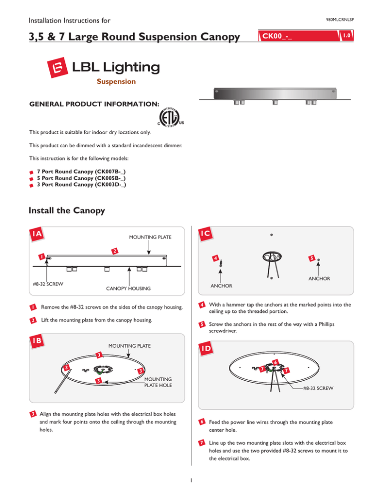
1
Remove the #8-32 screws on the sides of the canopy housing.
2
Lift the mounting plate from the canopy housing.
1B
MOUNTING PLATE
4
With a hammer tap the anchors at the marked points into the
ceiling up to the threaded portion.
5
Screw the anchors in the rest of the way with a Phillips
screwdriver.
1D
3
6
7
3
3
3
7
3
MOUNTING
PLATE HOLE
7
#8-32 SCREW
Align the mounting plate holes with the electrical box holes
and mark four points onto the ceiling through the mounting
holes.
1
6
Feed the power line wires through the mounting plate
center hole.
7
Line up the two mounting plate slots with the electrical box
holes and use the two provided #8-32 screws to mount it to
the electrical box.
1H
1E
8
FIXTURE CORD
8
8
13
MARKED POINT
8
CORD GRIP
#8 SCREW
12
CANOPY
CAP
8
Secure the mounting plate to the anchors with the provided
#8 screws.
12 When desired height is achieved, slightly tighten the cap.
1F
13 From inside the canopy mark the cord right behind the cord
grip for the strain relief location.
CANOPY
CORD GRIP
STRAIN
RELIEF
1I
9
15
CAP
SLOT HEAD
SCREW
MARKED POINT
9
For each of the canopies cord grips unscrew the caps.
1G
CORD GRIP
FIXTURE CORD
CANOPY
14
CAP
14 Loosen the cap and feed the cord through the strain relief.
CORD GRIP
15 Place the strain relief right above the marked point and tighten
CANOPY
10
the slot head screw.
CAP
16 Slide the canopy against the strain relief and tighten the cap to
the cord grip.
17 For power connection, leave at least 1’ of the cord exposed in
10 Feed the fixture cord through the cap and cord grip into the
the back of the canopy.
canopy.
18 Cut off excess cord with a sharp cutter.
11 Adjust the fixture height (from bottom of the fixture shade to
top of the canopy) by moving the fixture cord up or down.
2
1L
1J
MOUNTING
PLATE
SAFETY
BRACKET
22
19
SAFETY
CABLE
24
23
4"
19 From the end of the cord, strip the outer insulation 4" using a
sharp knife. Make sure not to cut inner wires.
20 Strip 1/4" of insulation from the inner insulated wires.
1K
MOUNTING
PLATE
SAFETY
BRACKET
HOUSING
21
22 Make sure the mounting plate is grounded in accordance with
local electrical codes.
SAFETY CABLE
23 Connect the neutral suspension cords to the neutral power
line wire and secure with a wire nut.
24 Connect the hot suspension cords to the hot power line wire
and secure with a wire nut.
25 Place all wires and wire nut connections properly inside
the housing.
21
1M
26
HOUSING
27
#8-32 SCREW
NOTE: It is recommended that one person holds the
canopy while the electrician finishes the installation.
26 Slide the housing onto the mounting plate and line up the
21 Insert one end of the safety cable into the mounting plate
housing holes with the mounting plate holes.
safety bracket and insert the other end into the housing safety
bracket.
27 Replace and tighten the #8-32 screws to secure the housing in
place.
3
SAVE THESE INSTRUCTIONS!
7400 Linder Ave, Skokie, IL 60077
800.323.3226 - 847.626.6300
www.lbllighting.com
© 2008 LBL Lighting. All rights reserved. The "LBL Lighting" graphic is a
registered trademark of LBL Lighting. LBL Lighting reserves the right to
change specifications for product improvements without notification.
A Generation Brands Company
4

