Product Specification
03258E
SG 2D
Speed Governor
APPLICATIONS
DESCRIPTION
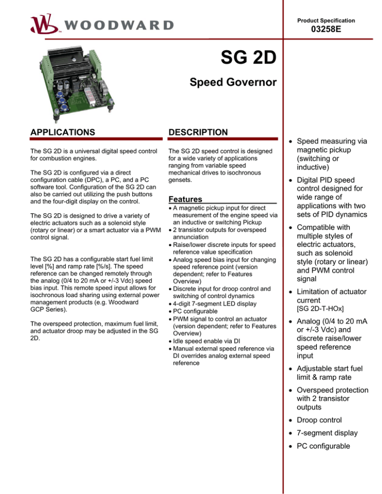
The SG 2D is a universal digital speed control
for combustion engines.
The SG 2D speed control is designed
for a wide variety of applications
ranging from variable speed
mechanical drives to isochronous
gensets.
The SG 2D is configured via a direct
configuration cable (DPC), a PC, and a PC
software tool. Configuration of the SG 2D can
also be carried out utilizing the push buttons
and the four-digit display on the control.
The SG 2D is designed to drive a variety of
electric actuators such as a solenoid style
(rotary or linear) or a smart actuator via a PWM
control signal.
The SG 2D has a configurable start fuel limit
level [%] and ramp rate [%/s]. The speed
reference can be changed remotely through
the analog (0/4 to 20 mA or +/-3 Vdc) speed
bias input. This remote speed input allows for
isochronous load sharing using external power
management products (e.g. Woodward
GCP Series).
The overspeed protection, maximum fuel limit,
and actuator droop may be adjusted in the SG
2D.
Features
• A magnetic pickup input for direct
measurement of the engine speed via
an inductive or switching Pickup
• 2 transistor outputs for overspeed
annunciation
• Raise/lower discrete inputs for speed
reference value specification
• Analog speed bias input for changing
speed reference point (version
dependent; refer to Features
Overview)
• Discrete input for droop control and
switching of control dynamics
• 4-digit 7-segment LED display
• PC configurable
• PWM signal to control an actuator
(version dependent; refer to Features
Overview)
• Idle speed enable via DI
• Manual external speed reference via
DI overrides analog external speed
reference
• Speed measuring via
magnetic pickup
(switching or
inductive)
• Digital PID speed
control designed for
wide range of
applications with two
sets of PID dynamics
• Compatible with
multiple styles of
electric actuators,
such as solenoid
style (rotary or linear)
and PWM control
signal
• Limitation of actuator
current
[SG 2D-T-HOx]
• Analog (0/4 to 20 mA
or +/-3 Vdc) and
discrete raise/lower
speed reference
input
• Adjustable start fuel
limit & ramp rate
• Overspeed protection
with 2 transistor
outputs
• Droop control
• 7-segment display
• PC configurable
SPECIFICATIONS
Transistor output.......................... NPN switching transistor
Rated switching voltage.............................................. 24 Vdc
Switching current (ohmic load) ..................................200 mA
Pickup signal........................................................... isolated
min. amplitude (sinusoidal) ......... 0.5 Veff (300 Hz to 8.0 kHz)
max. amplitude (sinusoidal) ............... 75 Veff (DC at 1.5 kHz)
75 to 150 Veff (1.5 to 8.0 kHz)
min. input impedance........... 18.8 kOhm (300 Hz to 8.0 kHz)
Accuracy (measured)............................. +/-0.12 to +/-0.25 %
(dep. on pos. in meas. range)
Housing
Mounting M......................................extrusion profile Um 108
to snap on a DIN-rail/C-profile
Mounting S ......................................vibration absorber M4×6
Actuator control ................................................PWM signal
Continuous duty ................ [SG 2D-T-Lx] 45 mA; [SG 2D-T-Hx] 7 A
Current carrying capacity [SG 2D-T-Lx] 80 mA; [SG 2D-T-Hx] 11 A
Power supply
[SG 2D-T-xx] 8 to 32 Vdc
Power consumption (control only) ................................ 1.5 W
Max. power consumption (actuator) ...........[SG 2D-T-Hx] 352 W
[SG 2D-T-Lx] 2.56 W
Ambient temperature ..........................................-20 to 70 °C
Ambient humidity ............................... 95 %, non-condensing
Dimensions [depending on type]
Mounting M.................................... max. 137 × 126 × 56 mm
Mounting S .................................... max. 135 × 108 × 43 mm
Drilling scheme for mounting S [depending on type]
Mounting S ......................................... 103/113/125 × 98 mm
Connection
Screw/plug terminal ................................1.5 mm² or 2.5 mm²
Weight [depending on type]...................... approx. 200/350 g
Discrete inputs........................................................ isolated
Input range...........................................................8 to 32 Vdc
Input resistance ........................................ approx. 6.7 kOhm
Protection system ........................................................IP 00
Disturbance test (CE) ............................ tested according to
applicable EN guidelines
Analog input............................................... resolution 10 Bit
Input 0/4 to 20 mA, load.......................................... 250 Ohm
Input +/-3 V DC, input resistance ............... approx. 40 kOhm
DIMENSIONS
54/56 mm
36/38 mm
115/124/137 mm
Some dimensions depend on the type of the unit.
Mounting over the printed-circuit board
113/122/135 mm
103/113/125 mm
4
5
6
7
8
SET
n [1/ m in ]
4 P
5 I [s ]
6 D [s ]
7
[% / s ]
8 S t a r t[% ]
9
[n o .]
(0 n [% ])
SET
9 10 11 12 13 14 15 16 17 18
RS232
teleph.
connect.
108 mm
3
98 mm
2
126 mm
1
Vibration absorber
screws: M4x6
Note:
If the unit is to be mounted
in the engine control box,
it is recommended that the
vibration isolation mounting
be utilized. DIN rail mounting
is not recommended for locations
where the control will experience vibrations
Subject to technical modifications.
2006-02-20 | SG 2D Dimensions sg2dww-0806-ab.SKF
1
-
2
+
3
-
4
+
5
-
+
6
-
18 17 16 15 14 13 12 11 10 9
lower
Discrete input
raise
Droop
Common
Transistor output 2
Transistor output 1
(0 V DC)
Input
+/-3 V DC
S..Virbration absorber
M..Snap-on rail installation
(OUT)
(+/-3 V DC)
Mounting
-
Input
0/4 to 20 mA
7
(IN)
Actuator (PWM signal)
8
6
+
8
-
7
Actuator (PWM signal)
Power supply
18 17 16 15 14 13 12 11 10 9
+
S..Virbration absorber
M..Snap-on rail installation
4
+
5
Power supply
Mounting
-
MPU
Order notes (e.g.)
SG 2D-T-HOM, SG 2D-T-HOS
2
+
3
MPU
lower
Discrete input
raise
Droop
Common
Transistor output 2
Order notes (e.g.)
SG 2D-T-LOVM, SG 2D-T-LOVS
1
WIRING DIAGRAMS
Transistor output 1
Configuration interface
RJ45 plug connected via DPC cable
to the RS-232 interface of the PC.
Configuration interface
RJ45 plug connected via DPC cable
to the RS-232 interface of the PC.
1
1
2
3
4
5
6
7
SG2-T-LOV
8
Rechange
SET
RS232
n [1/ m in ]
3 Im a x[A ]
4 P
5 I
[s ]
6 D
[s ]
7
[% / s ]
8 S t a r[%
t ]
9
[n o .]
(0 n [% ])
SET
9 10 11 12 13 14 15 16 17 18
Subject to technical modifications.
SG2D-T-HO
2006-01-10 | SG 2D-T Wiring Diagram sg2dww-0206-ap.SKF
SET
n [1/ m in ]
4 P
5 I
[s ]
6 D
[s ]
7
[% / s ]
8 S t a r [%
t ]
9
[n o .]
(0 n [% ])
SET
9 10 11 12 13 14 15 16 17 18
1
Subject to technical modifications.
SG 2D-T-LOV
S p ae
r
part
Ersatz
RS232
Fu sv
i el
re s ev
ra
SG 2D-T-HOx
1 2 3 4 5 6 7 8
2006-01-10 | SG 2D-T Wiring Diagram sg2dww-0206-ap.SKF
FEATURES OVERVIEW
Europe
Woodward Governor Company
Leonhard-Reglerbau GmbH
Handwerkstrasse 29
70565 Stuttgart, Germany
Ph: +49 (0) 711 789 54-0
Fax: +49 (0) 711 789 54-100
Distributors & Service
Woodward has an international
network of distributors and
service facilities. For your
nearest representative, call the
Fort Collins plant or see the
Worldwide Directory on our
website.
Corporate Headquarters
Rockford IL, USA
Ph: +1 (815) 877-7441
For more information contact:
www.woodward.com/power
Subject to technical
modifications.
This document is distributed for
informational purposes only. It is not
to be construed as creating or
becoming part of any Woodward
Governor Company contractual or
warranty obligation unless expressly
stated in a written sales contract.
We appreciate your comments
about the content of our
publications. Please send comments
including the document number
below to
stgt-doc@woodward.com
© Woodward Governor
Company
All Rights Reserved
03258E - 06/3/S
-T-LOV
-T-HOV
SG 2D
-T-HO
International
Woodward
PO Box 1519
Fort Collins CO, USA
80522-1519
1000 East Drake Road
Fort Collins CO 80525
Ph: +1 (970) 482-5811
Fax: +1 (970) 498-3058
Setpoint value via …
9
9
9
Internal
9
9
9
Discrete raise/lower
9
0/4 to 20 mA
9
9
+/- 3 Vdc
PWM control output via …
9
9
7 A continuous / 11 A peak
9
45 mA continuous / 85 mA peak
Protection output via …
9
9
9
Transistor
Compatible Actuators
9
Flo-TechTM
9
9
EPG 512, 524, 1712, 1724
Any commercial actuator with moving
9#1
9#1
9#1
coil and return spring
Power Supply
9
9
9
12/24 Vdc
Accessories
9
9
9
Configuration via PC #2
Listings/Approvals
9
9
9
CE
Product Number P/N
DIN rail mounting type M 8443-1006 8443-1001
Vibration absorber mounting type S 8443-1005 8443-1003 8443-1004
#1 Dependent on actuator
#2 Cable incl. software necessary (DPC, Product Number P/N 5417-557)


