An Introduction to the Operational Amplifier
advertisement

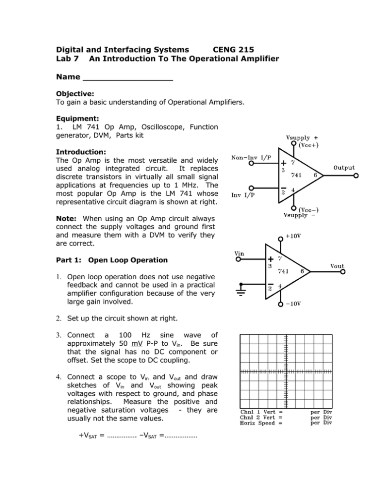
Digital and Interfacing Systems CENG 215 Lab 7 An Introduction To The Operational Amplifier Name _________________ Objective: To gain a basic understanding of Operational Amplifiers. Equipment: 1. LM 741 Op Amp, Oscilloscope, Function generator, DVM, Parts kit Introduction: The Op Amp is the most versatile and widely used analog integrated circuit. It replaces discrete transistors in virtually all small signal applications at frequencies up to 1 MHz. The most popular Op Amp is the LM 741 whose representative circuit diagram is shown at right. Note: When using an Op Amp circuit always connect the supply voltages and ground first and measure them with a DVM to verify they are correct. Part 1: Open Loop Operation 1. Open loop operation does not use negative feedback and cannot be used in a practical amplifier configuration because of the very large gain involved. 2. Set up the circuit shown at right. 3. Connect a 100 Hz sine wave of approximately 50 mV P-P to Vin. Be sure that the signal has no DC component or offset. Set the scope to DC coupling. 4. Connect a scope to Vin and Vout and draw sketches of Vin and Vout showing peak voltages with respect to ground, and phase relationships. Measure the positive and negative saturation voltages - they are usually not the same values. +VSAT = ……………. –VSAT =……………… Part 2: Closed Loop Inverting Amplifier A closed loop amplifier uses negative feedback. This involves taking a sample of the output voltage and ‘feeding it back’ so that it subtracts from the input voltage which reduces and stabilizes the voltage gain and results in many other benefits. 1. Set up the circuit shown at right, using a ± 10V supply. 2. Connect a 500 Hz sine wave of approx 200 – 300 mV with no DC offset to VIN. Use DC Coupling. Connect a scope at VIN and VOUT. Draw sketches of VIN and VOUT showing P-P voltages with respect to ground and phase relationships. Adjust the VIN signal so that VOUT is not saturated (not clipping at the top/bottom) before making your sketches. 3. Press the Measure button on the scope and record the values of VIN & VOUT VIN = .........………..... VOUT = ...........………...... Determine the closed loop voltage gain of the amplifier as: AV,CL = VOUT / VIN = ....................... Note: There are no units for GAIN, it is a simple Ratio of the output and input voltages. 4. Calculate the voltage gain of the amplifier as: AV,CL = - RF / R1 = .............. Note: The minus sign in the formula indicates the output of the amplifier is 180° out of phase with input. It does NOT indicate negative gain or attenuation. 5. Compare the Gain values found in steps 3 and 4. Do they agree? ……………… 6. Observe VOUT on the scope. Adjust the amplitude of VIN so that VOUT is, for example, exactly 6V P-P. 7. Increase the frequency until the amplitude of Vout has dropped to 0.707 of what it was in step 6. (0.707 * 6 V P-P = 4.2 V P-P). This frequency is the corner frequency or Bandwidth (BW) of the amplifier. fcorner = Bandwidth = .............................. 8. Replace RF with a 100 kΩ resistor and repeat steps 3, 4, 5, 6, and 7. VIN = ................ VOUT = ............... AV.CL = - RF / R1 = .................. AV,CL = VOUT / VIN = ..……......... fcorner = ........................ Did AV,CL increase or decrease when RF was increased to 100 kΩ? Did fcorner increase or decrease when RF was increased to 100 kΩ? Write a statement about Gain Vs Bandwidth: Procedure Part 3: Closed Loop Non-Inverting Amplifier 1. Set up the circuit shown below right. 2. Apply a 1 kHz sine wave of 200 – 300 mV (with no DC offset) to Vin. Adjust the Vin amplitude so the O/P does not saturate. Connect a scope at Vin and Vout. Draw sketches of Vin and Vout showing peak voltages with respect to ground and phase relationships. Be sure that Vout is not saturated before making your sketches. 3. Measure the closed loop voltage gain of the amplifier: VIN = ..…….… VOUT = .………..… AV,CL = VOUT / VIN = .........… 4. Calculate the voltage gain of the amplifier as AV.CL = 1+ (RF / R1 ) = .......... 5. Do the values found in steps 3 and 4 agree? …….... Voltage Follower A special case of the non inverting amplifier is the voltage follower. It uses 100% negative feedback. It is often used as a buffer between two circuits or an impedance matching device when a low O/P impedance is desirable. 6. Set up the circuit at right and replace RF with a piece of wire and remove R1. Make a calculation for the measured value using the equivalent values for RF and R1 . AV,CL = 1+ (RF / R1 ) Calculated AV,CL = .......... 7. Measure the voltage gain. VIN = .……........... VOUT = .….……........ Measured AV.CL = VOUT / VIN = ....…............. Do the calculated and measured values agree? ……….. Questions 1. In all op-amp circuits, the voltage difference between the inverting input and non-inverting inputs (between pins 2 & 3) is considered to be……………………………Volts 2. In your own words, state why most op-amps are not used as amplifiers in the open loop mode. 3. Explain briefly, in your own words, what effect negative feedback has on the voltage gain of a closed loop amplifier. 4. Decreasing voltage gain increases/decreases the band width (corner or cut off frequency fcorner) Signed ………………………………………… Date……………………….


