Frequency Response of an Ideal Integrator The
advertisement
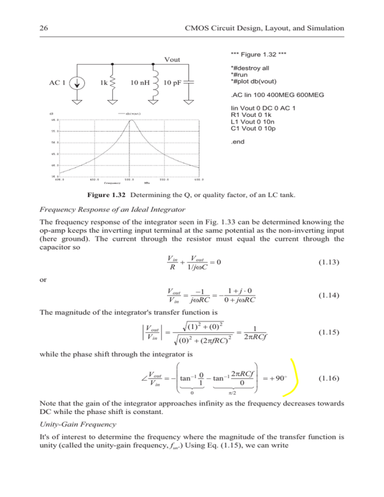
26 CMOS Circuit Design, Layout, and Simulation *** Figure 1.32 *** Vout AC 1 1k 10 nH *#destroy all *#run *#plot db(vout) 10 pF .AC lin 100 400MEG 600MEG Iin Vout 0 DC 0 AC 1 R1 Vout 0 1k L1 Vout 0 10n C1 Vout 0 10p .end Figure 1.32 Determining the Q, or quality factor, of an LC tank. Frequency Response of an Ideal Integrator The frequency response of the integrator seen in Fig. 1.33 can be determined knowing the op-amp keeps the inverting input terminal at the same potential as the non-inverting input (here ground). The current through the resistor must equal the current through the capacitor so V in V out R 1/jZC (1.13) 0 or V out V in 1 jZRC 1j0 0 jZRC (1.14) The magnitude of the integrator's transfer function is V out V in 1 2 0 2 0 2SfRC 2 2 1 2SRCf (1.15) while the phase shift through the integrator is V out V in § · ¨ 1 0 ¸ 2SRCf ¨ tan tan 1 ¸ 1 0 ¨ ¸ © 0 ¹ S/2 90 (1.16) Note that the gain of the integrator approaches infinity as the frequency decreases towards DC while the phase shift is constant. Unity-Gain Frequency It's of interest to determine the frequency where the magnitude of the transfer function is unity (called the unity-gain frequency, fun.) Using Eq. (1.15), we can write


