Agilent 30 MHz Function/Arbitrary Waveform Generators
advertisement
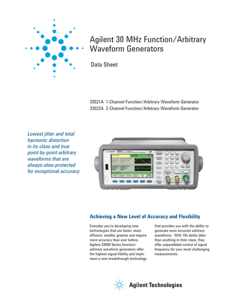
Agilent 30 MHz Function/Arbitrary Waveform Generators Data Sheet 33521A 1-Channel Function/Arbitrary Waveform Generator 33522A 2-Channel Function/Arbitrary Waveform Generator Lowest jitter and total harmonic distortion in its class and true point-by-point arbitrary waveforms that are always alias-protected for exceptional accuracy Achieving a New Level of Accuracy and Flexibility Everyday you’re developing new technologies that are faster, more efficient, smaller, greener and require more accuracy than ever before. Agilent 33500 Series function/ arbitrary waveform generators offer the highest signal fidelity and implement a new breakthrough technology that provides you with the ability to generate more accurate arbitrary waveforms. With 10x better jitter than anything in their class, they offer unparalleled control of signal frequency for your most challenging measurements. 33500 Series Function/Arbitrary Waveform Generators Key features • 30 MHz sine, square, and pulse bandwidth cover more applications • < 40 ps jitter and less than .04% total harmonic distortion for more precise signals • 250 MSa/s, 16-bit sampling rate for higher time-resolution arbitrary waveforms • True point-by-point arbitrary waveforms with sequencing for more accurate representation of user-defined signals • Dual-channel mode with independent or coupled channels • 1 MSa waveform memory standard, 16 MSa (optional) for more complicated arbitrary waveforms • LXI Class C compliant • Large, color, graphical display allows for simultaneous parameter setup and signal viewing/editing for intuitive operation • Optional BenchLink Waveform Builder Pro software for custom user-defined waveforms Signal fidelity You depend upon the fidelity of generated signals to verify the development of your designs. The higher the fidelity of the generated signal, the more assurance the device under development will perform to your exacting standards. The 33500 Series function/arbitrary waveform generators have < 40 ps jitter for any signal ― ten times better than existing function/arbitrary waveform generators. They provide 16-bit resolution, which is the highest resolution in their class. Combined with less than .04% total harmonic distortion and 250 MSa/s, 16-bit sampling, optional high-stability timebase and optional arbitrary waveform memory expansion, you now have access to an affordable new family of generators with unparallel signal fidelity. Flexible signal generation The 33521A and 33522A have the ability to create two-tone signals for dual-tone multi-frequency (DTMF) signal applications used in telecommunication device test. A feature specific to the 33522A generator is a flexible, dual-channel mode with frequency and amplitude coupling, differential channels, and combined output channels. This functionality is useful in applications where testing a device, such as a pacemaker, relies on the timing and interaction of two distinct signals to operate properly. Point-by-point waveforms The 33500 Series expands your signaling capability with true pointby-point arbitrary waveforms that are always alias-protected for exceptional accuracy. The 33521A and 33522A are first in their class to generate 30 MHz signals, including common waveforms, arbitrary waveforms and sophisticated modulated waveforms. Both models leverage proprietary technology to provide you with 2 unprecedented input control when defining arbitrary waveforms. That control equates to the ability to define more complex point-by-point waveforms with sequencing. User interface A large, color, graphical display offers simultaneous parameter setup, signal viewing, and editing for easy operation. The 33500 Series is fully compliant with the LXI Class C specifications and offers USB 2.0 and 10/100 Base-T Ethernet connectivity for quick and easy connectivity to a PC or network. The 33500 Series also supports remote operation using a browser to connect to a built-in Web page. GPIB is offered as an optional interface. Optional 33503A BenchLink Waveform Builder Pro Softrware Benchlink Waveform Builder Pro is ideal for R&D engineers characterizing new designs and test system engineers validating production units. The software is a Microsoft Windows®-based program that provides easy-to-use creation tools, such as an equation editor, waveform math and drawing tools, which can be used to create custom signals. It features a standard function library, waveform sequencer, and filters and; as well as windowing functions that allow you to easily modify and further refine your waveform. A library of built-in signals supports fast creation of more complex waveforms. With BenchLink Waveform Builder Pro, you gain access to advanced signal creation and editing capabilities, without requiring hours of programming. The result is quicker, easier creation of custom waveforms, coupled with deeper analysis insight into your signals. For additional information and to download a 30-day trial version of the software, visit: www.agilent.com/find/33503 Specifications Unless otherwise stated, all specifications apply with a 50 Ω resistive load and auto range ON. Instrument characteristics Models & options 33521A 1-channel 33522A 2-channel Option 002 Increases arbitrary waveform memory to 16 MSa/channel Option 010 OCXO timebase for ultra-high stability Option 400 GPIB interface Waveforms Standard Sine, square, ramp, pulse, triangle, Gaussian noise, PRBS (Pseudorandom Binary Sequence), DC Built-in arbitrary Cardiac, exponential fall, exponential rise, Gaussian pulse, Haversine, Lorentz, D-Lorentz, negative ramp, sinc User-defined arbitrary Up to 1 MSa (16 MSa with Option 002) with multi-segment sequencing Operating modes & modulation types Operating modes Continuous, modulate, frequency sweep, burst, output gate Modulation types AM, FM, PM, FSK, BPSK, PWM, Sum (carrier + modulation) Waveform characteristics Sine Frequency range 1 µHz to 30 MHz, 1-µHz resolution 1, 2 Amplitude flatness (spec) (relative to 1 kHz) Harmonic distortion (typ) 2, 3 THD (typ) Non-harmonic spurious (typ) 2, 3 Phase noise (SSB) (typ) 1 kHz offset: 10 kHz offset: 100 kHz offset: < 100 kHz: 100 kHz to 5 MHz: 5 to 20 MHz: 20 to 30 MHz: ± 0.10 dB ± 0.15 dB ± 0.30 dB ± 0.40 dB < 20 kHz: < -70 dBc 20 to 100 kHz: 100 kHz to 1 MHz: 1 to 20 MHz: 20 to 30 MHz: < -65 dBc < -50 dBc < -40 dBc < -35 dBc 20 Hz to 20 kHz: < 0.04% Standard: < -75 dBc, increasing +20 dB/decade above 2 MHz Option 010: < -75 dBc, increasing +20 dB/decade above 10 MHz (or < -100 dBm, whichever is greater, below 500 MHz) Standard -105 -115 -125 Option 010 -110 dBc/Hz -125 dBc/Hz - 135 dBc/Hz 3 Waveform characteristics, continued Square & pulse Frequency range 1 µHz to 30 MHz, 1 µHz resolution Rise and fall times (nom) Square: 8.4 ns, fixed Pulse: 8.4 ns to 1 µs, independently variable, 100-ps or 3-digit resolution Overshoot (typ) < 2% Duty cycle 0.01% to 99.99% 8 Pulse width 16 ns minimum, 100-ps resolution Jitter (cycle-to-cycle, typ) < 40 ps rms Ramp & triangle Frequency range 1 µHz to 200 kHz, 1 µHz resolution Ramp symmetry 0.0% to 100.0%, 0.1% resolution (0% is negative ramp, 100% is positive ramp, 50% is Triangle) Nonlinearity (typ) < 0.05% from 5% to 95% of the signal amplitude Gaussian noise Bandwidth (typ) 1 mHz to 30 MHz, variable Crest factor (nom) 4.6 Repetition period > 50 years Pseudorandom binary sequence (PRBS) Bit rate 1 mbps to 50 Mbps, 1 mbps resolution Sequence length 2m -1, m=7, 9, 11, 15, 20, 23 Rise and fall times (nom) 8.4 ns to 1 µs, variable, 100-ps or 3-digit resolution Arbitrary waveform characteristics General Waveform length 8 Sa to 1 MSa (16 MSa with Option 002) in increments of 1 sample Sample rate 1 µSa/s to 250 MSa/s, 1 µSa/s resolution Voltage resolution 16 bits Bandwidth (-3 dB, nom) Filter Off: 40 MHz “Normal” Filter On: 0.27 x (Sample Rate) “Step” Filter On: 0.13 x (Sample Rate) Rise and fall time 0.35 / Bandwidth (10 ns min) with "Normal" or "Step" filter On Settling time (typ) < 200 ns to 0.5% of final value Jitter (typ) Filter Off: < 40 ps rms “Normal” or “Step” filter On: 4 < 5 ps Arbitrary waveform characteristics, continued Waveform sequencing Operation Individual arbitrary waveforms (segments) can be combined into user-defined lists (sequences) to form longer, more complex waveforms. Each sequence step specifies whether to repeat the associated segment a certain number of times, to repeat it indefinitely, to repeat it until a Trigger event occurs, or to stop and wait for a Trigger event. Additionally, the behavior of the Sync output can be specified in each step. To improve throughput, up to 32 sequences totalling up to 1,024 segments can be preloaded into volatile memory. Segment length 8 Sa to 1 MSa (16 MSa with Option 002) in increments of 1 sample Sequence length 1 to 512 steps Segment repeat count 1 to 1x10⁶, or infinite Output characteristics Isolation Outputs Connector shells for channel output(s), Sync, and Mod In are connected together but isolated from the instrument’s chassis. Maximum allowable voltage on isolated connector shells is ±42 Vpk Signal output Output impedance (nom) 50 Ω On, off, inverted User-selectable for each channel Voltage limit User-definable VMAX and VMIN limits Overload protection Output turns off automatically when an overload is applied Instrument will tolerate a short-circuit to ground indefinitely Amplitude Range 1 mVpp to 10 Vpp into 50 Ω 2 mVpp to 20 Vpp into open circuit Resolution 4 digits Units Vpp, Vrms, or dBm, selectable Accuracy 1, 2 (spec) ±1% of setting ±1 mVpp at 1 kHz DC offset Range 5 ±(5 VDC - Peak AC) into 50 Ω ±(10 VDC - Peak AC) into open circuit Resolution 4 digits Units VDC Accuracy 1, 2 (spec) ±1% of Offset setting ±0.25% of Amplitude setting ±2mV Frequency accuracy Standard frequency reference (spec) 1 year, 23°C ± 5°C ±1 ppm of setting ± 15 pHz 1 year, 0°C to 55°C ±2 ppm of setting ± 15 pHz High-stability frequency reference (spec): Option 010 1 year, 0°C to 55°C ±0.1 ppm of setting ± 15 pHz 5 Modulation types and operating modes Carrier AM FM PM FSK BPSK Sine and Square ● ● ● ● ● Pulse ● ● ● ● ● Triangle and Ramp ● ● ● ● ● Gaussian Noise ● PRBS ● Single ARB ● Sequenced ARB ● ● PWM ● ● b b ● ● Sum Burst Sweep ● ● ● ● ● ● ● ● ● ● a ● ● ● ● ● ● a. Gated burst only. b. Applies to sample clock, not whole waveform. Modulating signals Carrier Sine Square Triangle / Ramp Noise PRBS ARB External Sine ● ● ● ● ● ● ● Square and Pulse ● ● ● ● ● ● ● Triangle and Ramp ● ● ● ● ● ● ● Gaussian Noise ● ● ● PRBS ● ● ● ● ● ARB ● ● ● ● ● Modulation characteristics Amplitude modulation (AM) Source Internal or external, or either channel with 33522A Type Full-carrier or double-sideband suppressed-carrier Depth 1 0% to 120%, 0.01% resolution Frequency modulation (FM) 7 Source Internal or external, or either channel with 33522A Deviation 1 µHz to 15 MHz, 1 µHz resolution Phase modulation(PM) Source Internal or external, or either channel with 33522A Deviation 0° to 360°, 0.1° resolution Frequency shift key modulation (FSK) 7 Source Internal timer or ext trig connector Mark & space Any frequency within the carrier signal's range Rate 0 Hz to 1 MHz Binary phase shift key modulation (BPSK) Source Internal timer or ext trig connector Phase shift 0° to 360°, 0.1° resolution Rate 0 Hz to 1 MHz Pulse width modulation (PWM) Source Deviation Internal or external, or either channel with 33522A 8 0% to 100% of pulse width, 0.01% resolution Additive modulation (Sum) Source Ratio 6 Internal or external, or either channel with 33522A 0% to 100% of carrier amplitude, 0.01% resolution 6 ● ● ● ● ● Burst 9 Type Counted or gated Count 1 to 1x10⁸ cycles, or infinite Gated Produces complete cycles while Ext Trig is asserted Start/stop phase 4 -360° to 360°, 0.1° resolution Trigger source Internal Timer or Ext Trig connector Marker Adjustable to any cycle; indicated by the trailing edge of the Sync pulse Sweep 7 Type Linear, Logarithmic, List (up to 128 user-defined frequencies) Operation Linear and Logarithmic sweeps are characterized by a Sweep time (during which the frequency changes smoothly from Start to Stop), a Hold time (during which the frequency stays at the Stop frequency), and a Return time (during which the frequency changes smoothly from Stop to Start). Returns are always linear. Direction Up (Start freq < Stop freq) or Down (Start freq > Stop freq) Start and stop frequencies Any frequency within the waveform's range Sweep time Linear: 1 ms to 3600 s, 1 ms resolution; 3601 s to 250,000 s, 1 s resolution Logarithmic: 1 ms to 500 s Hold time 0 s to 3600 s, 1 ms resolution Return time Trigger source 0 s to 3600 s, 1 ms resolution 10 Marker Immediate (continuous), external, single, bus, or timer Adjustable to any frequency between Start and Stop for Linear and Logarithmic types or any frequency in the list for List type; indicated by the trailing edge of the sync pulse Internal timer for FSK, BPSK, BURST, and SWEEP Range 1 µs to 8000s, 6-digit or 4 ns resolution 2-channel characteristics (33522A only) Operating modes Independent, coupled parameter(s), combined (Ch 1 + Ch 2), Equal (Ch 2 = Ch 1), or differential (Ch 2 = -Ch 1) Parameter coupling None, frequency (ratio or difference) and/or amplitude and DC offset Relative phase 0° to 360°, 0.1° resolution Skew (typ) < 200 ps (when performing identical operations) Crosstalk (typ) < -85 dB 7 Sync/marker output Connector Front-panel BNC, isolated from chassis Functions Sync, sweep marker, burst marker, or arbitrary waveform marker Assignment Channel 1 or channel 2 Polarity Normal or inverted Voltage level (nom) 3 Vpp into open circuit, 1.5 Vpp into 50 Ω Output impedance (nom) 50 Ω Minimum pulse width (nom) 16 ns External trigger/gate Connector Rear-panel BNC, chassis-referenced Function Input or output Assignment Channel 1, channel 2, or both (as input) Channel 1 or channel 2 (as output) Polarity Positive or negative slope Voltage level (nom) 0 V to 0.4 V for low, > 2.3 V for high, 3.5 V maximum (as input) 3 Vpp (nom) into open circuit, 1.5 Vpp (nom) into 50 Ω (as output) Impedance (nom) 10 k Ω, DC-coupled (as input) 50 Ω (as output) Minimum pulse width (nom) 16 ns Input rate DC to 1 MHz Minimum pulse width 100 ns (as input) Duty cycle (nom) 50% (as output) Trigger delay 0 s to 1000 s, 4 ns resolution; applies to all trigger events Input latency (typ) < 135 ns with Trigger Delay set to zero Input jitter (typ) < 2.5 ns, rms Fanout <= 4 total Agilent 33521A and 33522A Modulation input Connector Rear-panel BNC, isolated Assignment Channel 1, Channel 2, or both Voltage level ±5 V full-scale Input impedance (nom) 5kΩ Bandwidth (-3 dB, typ) 0 Hz to 100 kHz Frequency reference input Connector Rear-panel BNC, isolated from chassis and all other connectors Reference selection Internal, external, or auto Frequency range Standard: 10 MHz ± 20 Hz Option 010: 10 MHz ± 1 Hz Lock time (typ) <2 s Voltage level 200 mVpp to 5 Vpp Input Impedance (nom) 1 k Ω || 20 pF, AC-coupled 8 Frequency reference output Connector Rear-panel BNC, chasis-referenced Frequency (nom) 10 MHz Output impedance (nom) 50 Ω, AC-coupled Level (nom) 0 dBm, 632 mVpp into 50 Ω Real-time clock/calendar Set and read Year, month, day, hour, minute, second Battery CR-2032 coin-type, replacable, >5-year life (typ) Programming times (meas.) Configuration change speed LAN (socket) Change function LAN (VXI-11) USB 2.0 GPIB 5 ms 6 ms 5 ms 5 ms Change frequency 2 ms 3 ms 2 ms 3 ms Change amplitude 20 ms 20 ms 19 ms 22 ms 9 ms 11 ms 9 ms 9 ms LAN (VXI-11) USB 2.0 GPIB Select user arb (16 k) Arbitrary waveform download speed to volatile (binary transfer) LAN (socket) 4 k sample 6 ms 18 ms 8 ms 39 ms 1 M sample 1.3 s 2.6 s 13 s 9.1 s Memory Arbitrary waveform and instrument state memory Volatile 1x10⁶ samples per channel or 16x106 samples per channel (Option 002) 512 sequence steps per channel Non-volatile File sytem file space is limited to 64 MB (~32 MSa of arbitrary waveform records) Instrument state Store / Recall User defined instrument states Power Off Power Off state automatically saved Power On Factory default settings or last power off settings USB File System Front-panel port USB 2.0 high-speed mass storage (MSC) class device Capability Read or write instrument configuration settings, instrument states and user arbitrary waveform and sequence files. Speed 10 MB/s (nom) 9 General characteristics Computer interfaces LXI- C (rev1.3) 10/100Base-T Ethernet (Sockets & VXI-11 protocol) USB2.0 (USB-TMC488 protocol) GPIB/IEEE-488.1, IEEE-488.2 Web user interface Remote operation and monitoring Programming language SCPI-1999, IEEE-488.2 Agilent 33210A / 33220A compatibile Graphical display 4.3" Color TFT WQVGA (480x272) with LED backlight Mechanical Size 261.1mm W x 103.8mm H x 303.2mm D (with bumpers installed) 212.8mm W x 88.3mm H x 272.3mm D (with bumpers removed) 2U x ½ rack width Weight (nom) 3.3 kg (7.2 lbs) Environmental Storage temperature -40˚C to 70˚C Warm-up time 1 hour Operating environment EN61010, polution degree 2; indoor locations Operating temperature 0˚C to 55˚C Operating humidity 5% to 80% RH, non-condensing Operating altitude up to 3000 meters Regulatory Safety Complies with European Low Voltage Directive and carries the CE-marking. Conforms to UL 61010-1, CSA C22.2 61010-1, and IEC 61010-1:2001 EMC Complies with European EMC Directive for test and measurement products. - IEC/EN 61326-1 - CISPR Pub 11 Group 1, class A - AS/NZS CISPR 11 - ICES/NMB-001 Complies with Australian standard and carries C-Tick mark This ISM device complies with Canadian ICES-001. Cet appareil ISM est conforme a la norme NMB-001 du Canada Acoustic Noise (nom) SPL 35 dB(A) Line power Voltage 100 V - 240 V 50/60 Hz -5%, +10% 100 V - 120 V 400 Hz ±10% Power consumption (typ) < 45 W, < 130 VA Warranty 1 year standard, 3 years optional 10 Definitions Specification (spec) The warranted performance of a calibrated instrument that has been stored for a minimum of 2 hours within the operating temperature range of 0ºC - 55ºC and after a 45-minute warm up period. All specifications include measurement uncertainty and were created in compliance with ISO-17025 methods. Data published in this document are specifications (spec) only where specifically indicated. Typical (typ) The characteristic performance, which 80% or more of manufactured instruments will meet. This data is not warranted, does not include measurement uncertainty, and is valid only at room temperature (approximately 23ºC). Nominal (nom) The mean or average characteristic performance, or the value of an attribute that is determined by design such as a connector type, physical dimension, or operating speed. This data is not warranted and is measured at room temperature (approximately 23ºC). Measured (meas) An attribute measured during development for purposes of communicating the expected performance. This data is not warranted and is measured at room temperature (approximately 23ºC). Accuracy Represents the traceable accuracy of a specified parameter. Includes measurement error and timebase error, and calibration source uncertainty. Random measuremet errors are combined using the root-sum-square method and are multiplied by M for the desired Confidence Level. Syatematic errors are added linearly and include time skew errors, trigger timing errors, and timebase errors as appropriate for each measurement type. Confidence Level For 99% Confidence use k= 2.5 in accuracy calculations. For 95% Confidence use k= 2.0 in accuracy calculations. 1. Add 1/10th of the output amplitude and offset accuracy specification per °C for operation at temperatures beyond 23°C ± 5°C. 2. Auto range ON. 3. DC Offset set to zero. 4. limited to arbitrary waveforms that are < 1 million points; phase resolution limited by number of points in arbitrary waveforms < 3,600 points. 5. Output noise is typically 20 dB lower when (DC + Peak AC) < 320 mV (into 50 Ω) or 640 mV (into open circuit). 6. Subject to maximum output voltage limits. 7. All frequency changes are phase-continuous. 8. Subject to pulse width limits. 9. Counted Burst operation is not allowed for Gaussian Noise. 10. External trigger only for sweep time > 8000 sec. 11 www.agilent.com www.agilent.com/find/33500 Agilent Email Updates www.agilent.com/find/emailupdates Get the latest information on the products and applications you select. www.lxistandard.org LXI is the LAN-based successor to GPIB, providing faster, more efficient connectivity. Agilent is a founding member of the LXI consortium. For more information on Agilent Technologies’ products, applications or services, please contact your local Agilent office. The complete list is available at: Agilent Advantage Services is committed to your success throughout your equipment’s lifetime. We share measurement and service expertise to help you create the products that change our world. To keep you competitive, we continually invest in tools and processes that speed up calibration and repair, reduce your cost of ownership, and move us ahead of your development curve. Agilent Channel Partners www.agilent.com/find/channelpartners Get the best of both worlds: Agilent’s measurement expertise and product breadth, combined with channel partner convenience. Windows® is a registered trademark of Microsoft Corporation in the United States and other countries. www.agilent.com/find/contactus Americas Canada Brazil Mexico United States (877) 894 4414 (11) 4197 3500 01800 5064 800 (800) 829 4444 Asia Pacific Australia China Hong Kong India Japan Korea Malaysia Singapore Taiwan Other AP Countries 1 800 629 485 800 810 0189 800 938 693 1 800 112 929 0120 (421) 345 080 769 0800 1 800 888 848 1 800 375 8100 0800 047 866 (65) 375 8100 www.agilent.com/quality Europe & Middle East Belgium 32 (0) 2 404 93 40 Denmark 45 70 13 15 15 Finland 358 (0) 10 855 2100 France 0825 010 700* *0.125 €/minute Germany Ireland Israel Italy Netherlands Spain Sweden United Kingdom 49 (0) 7031 464 6333 1890 924 204 972-3-9288-504/544 39 02 92 60 8484 31 (0) 20 547 2111 34 (91) 631 3300 0200-88 22 55 44 (0) 118 9276201 For other unlisted Countries: www.agilent.com/find/contactus Revised: October 14, 2010 Product specifications and descriptions in this document subject to change without notice. © Agilent Technologies, Inc. 2011 Printed in USA, June 3, 2011 5990-5914EN
