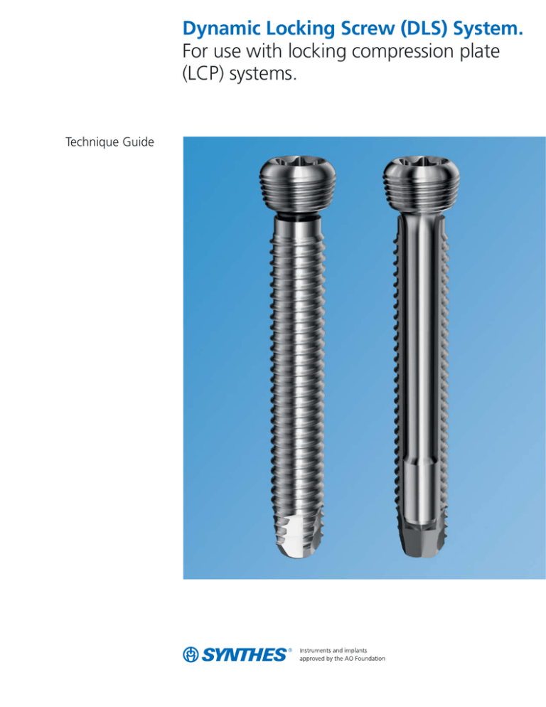
Dynamic Locking Screw (DLS) System.
For use with locking compression plate
(LCP) systems.
Technique Guide
Table of Contents
Introduction
Surgical Technique
Product Information
Dynamic Locking Screw (DLS) System
2
Locking Compression Plate (LCP)
4
AO Principles
5
Indications and Contraindications
6
Preparation
7
Dynamic Locking Screw Technique
8
Implant Removal
13
Implants
14
Instruments
– for 3.7 mm DLS Screws
– for 5.0 mm DLS Screws
15
16
Set Lists
18
Image intensifier control
Dynamic Locking Screw System
Technique Guide
Synthes
Dynamic Locking Screw (DLS) System.
For use with locking compression plate (LCP) systems.
Features
Angular stable screw
Locking screws can be placed in each
threaded hole of the appropriate LCP
plate.
StarDrive recess for improved
torque transmission*.
Screws locking tightly in the plate are
designed to:
– aid in minimizing tension on the
bone
– aid in minimizing compression
between plate and bone
– aid in protecting the periosteum
from potential damage and retain
circulation
Pin-sleeve design of the DLS allows
micro-motion within the angular stable
system.
Cobalt chromium molybdenum
alloy (CoCrMo) enables DLS to be
used with all Synthes stainless steel
or titanium locking large and small
fragment plates.
Laserwelded. For stable fixation
between pin and sleeve.
*Testing on file at Synthes.
2
Synthes
Dynamic Locking Screw System
Technique Guide
Principle of Dynamic Locking Screw (DLS)
Standard locking
head. Compatible
with all Synthes large
and small fragment
locking plates.
DLS allows surgeons to modulate the
rigidity of the locking plate construct.
Pin-sleeve design.
Micro-motion within
the screw.
DLS construct can deliver nearly parallel
fracture site motion.
Fully threaded
shaft. With locking
screw profile.
New screw tip. Rounded
tip with self-tapping flute
design.
Dynamic Locking Screw System
Technique Guide
Synthes
3
Locking Compression Plate (LCP)
The Synthes Locking Compression
Plate:
– Provides angular stable support of
fragments regardless of bone quality
– Is designed to reduce risk of primary
and secondary loss of reduction
even under high dynamic loading
– Is designed to reduce impairment of
periosteal blood supply due to limited
plate-periosteum contact
– Is designed to maintain a favorable
hold in osteoporotic bone and multiple fragment fractures
Locking Compression Plates have
combination locking and
compression holes (Combi holes).
The Combi holes allow placement of
standard cortex and cancellous bone
screws on one side or threaded conical
locking screws on the opposite side of
each hole.
a. Threaded hole section for locking
screws
b. Dynamic compression unit (DCU)
hole section for standard screws
c. Locking screw in threaded side of
plate hole
d. Cortex screw in compression side
of plate hole
d
c
a
b
Note: Holes in straight and reconstruction plates are oriented so that the
compression component of the hole is
always directed toward the middle of
the plate.
4
Synthes
Dynamic Locking Screw System
Technique Guide
AO Principles
In 1958, the AO formulated four basic principles, which
have become the guidelines for internal fixation.1 They are:
Anatomic reduction
Fracture reduction and fixation to restore anatomical
relationships.
Stable fixation
Stability by fixation or splintage, as the personality of the
fracture and injury requires.
Preservation of blood supply
Preservation of the blood supply to soft tissue and bone
by careful handling.
Early, active mobilization
Early and safe mobilization of the part and the patient.
1. M.E. Muller, M. Allgöwer, R. Schneider, and H. Willenegger:
Manual of Internal Fixation, 3rd Edition. Berlin: Springer-Verlag. 1991.
Dynamic Locking Screw System
Technique Guide
Synthes
5
Indications and Contraindications
Indications
Synthes Dynamic Locking Screws (DLS) in combination with
Synthes Locking Compression Plates (LCP) are intended for
use in long bone fractures, the fixation of osteopenic bone,
the fixation of osteotomies, and for the fixation of nonunions
and malunions.
Contraindications
– Severe muscular, neural or vascular diseases that endanger
the extremities involved
– Lack of bone substance or poor bone quality which makes
stable seating of the implant impossible
– Acute or chronic, local or systemic infections, and allergy
to the implanted material
The Synthes Dynamic Locking Screws are not approved
for screw attachment or fixation to the posterior elements
(pedicles) of the cervical, thoracic, or lumbar spine. The
adverse events that could occur are infection*, cardiovascular
disorder*, hematoma*, malunion or nonunion.
* These risks can also be associated with general risks of surgery.
6
Synthes
Dynamic Locking Screw System
Technique Guide
Preparation
Synthes offers a wide selection of LCP plates, which cover
a variety of indications. For this reason, this technique guide
does not cover specific indications or the selection of a plate
type for specific clinical situations. For these subjects, please
refer to “AO Principles of Fracture Management” courses
offered by the AO Foundation (www.aofoundation.org),
and the corresponding professional literature.
For general purposes, the following techniques for handling
the implants and instruments will be demonstrated with a
straight 3.5 mm LCP plate and 3.7 mm DLS.
Important: The 3.7 mm DLS has a 0.2 mm larger diameter
compared to the standard 3.5 mm locking screw. Therefore,
dedicated instruments for 3.7 mm DLS (drill bit and drill
sleeve) have to be used. All other instruments are the same
as standard locking small fragment technique.
Note: The 5.0 mm DLS is inserted per standard 5.0 mm
locking screw technique.
Required sets are dependent on the plates used. For small
fragment plates:
105.434
Small Fragment LCP Instrument and Implant
Set, with self-tapping screws
or
145.434
Small Fragment LCP Instrument and Titanium
Implant Set, with self-tapping screws
or
01.212.005
Small Fragment LCP Instrument and Implant
Set, with 3.5 mm StarDrive Cortex Screws
or
01.212.006
Small Fragment LCP Instrument and Implant
Set, with 3.5 mm Hex Drive Cortex Screws
or
01.212.007
Small Fragment LCP Instrument and Implant
Set, with 4.0 mm Cannulated Screws
or
01.212.008
Small Fragment LCP Instrument and Titanium
Implant Set, with 3.5 mm StarDrive Cortex
Screws
or
01.212.009
Small Fragment LCP Instrument and Titanium
Implant Set, with 3.5 mm Hex Drive Cortex
Screws
and
01.213.003
3.7 mm DLS Instrument Set
Note: The 3.7 mm DLS requires the use of:
03.213.001
3.1 mm Drill Guide, for 3.7 mm Dynamic
Locking Screw
and
03.213.002
3.1 mm Drill Bit, quick coupling, 165 mm
length, for 3.7 mm Dynamic Locking Screw
Do not insert the 3.7 mm DLS using the 2.8 mm Drill Bit
used for 3.5 mm Locking Screws.
Dynamic Locking Screw System
Technique Guide
Synthes
7
Dynamic Locking Screw Technique
1
Reduce fracture
Reduce the fracture under image intensification and, as needed,
provide fixation with a Kirschner wire or reduction forceps.
2
Contour plate
Instruments
329.04
Bending Iron, for 2.7 mm and 3.5 mm
plates, 150 mm length (for use with
329.05)
329.05
Bending Iron, for 2.7 mm and 3.5 mm
plates, 150 mm length (for use with
329.04)
329.15
Bending Pliers, for 2.7 mm and 3.5 mm
plates, 230 mm length
329.29
Bending Pliers, for 2.7 mm and 3.5 mm
Reconstruction Plates, 246 mm length
Adapt the LCP plate to the anatomy using the appropriate
bending instruments (as for standard plates).
Note: The LCP Combi holes are asymmetrical in the plate.
In straight plates, the hole alignment changes in the middle
of the plate. This asymmetry enables exertion of unidirectional
dynamic compression.
8
Synthes
Dynamic Locking Screw System
Technique Guide
Dynamic Locking Screw Technique
3
Position plate
Position and fix the plate on the bone.
Important:
Before setting the first dynamic locking screw, verify that the
plate is provisionally fixed in place. Otherwise, the plate may
rotate during final tightening and cause damage to surrounding soft tissue.
4
Insert DLS drill sleeve
Instrument
03.213.001
3.1 mm Drill Guide, for 3.7 mm Dynamic
Locking Screw
Carefully thread the drill guide into the desired LCP hole until
it is secure. The drill sleeve ensures that the DLS is correctly
aligned with the locking hole in the plate. Angular stability
is reduced if a locking screw is inserted obliquely.
Technique tip: If alignment is difficult, it may be useful to
slightly rotate the drill sleeve counterclockwise.
Note: In precontoured plates, the threaded hole is typically
not perpendicular to the plate surface due to the anatomy.
Important: Only use the white color-coded DLS drill guide
with the white color-coded drill bit for 3.7 mm DLS. The
5.0 mm DLS uses the same instruments as the 5.0 mm LCP.
Dynamic Locking Screw System
Technique Guide
Synthes
9
Dynamic Locking Screw Technique
5
Predrill screw hole
Instrument
03.213.002
3.1 mm Drill Bit, quick coupling,
165 mm length, for 3.7 mm Dynamic
Locking Screw
Carefully drill the screw hole using an appropriate drill.
Remove the drill sleeve.
Important: Only use the white color-coded DLS drill bit to
ensure the correct drill hole.
6
Determine screw length
Instrument
319.01
Depth Gauge
Determine screw length with the depth gauge.
10
Synthes
Dynamic Locking Screw System
Technique Guide
7
Insert Dynamic Locking Screw
Instruments
311.43
Handle, with quick coupling
314.116
StarDrive Screwdriver Shaft, T15,
self-retaining, quick coupling
511.773
Torque Limiting Attachment, 1.5 Nm,
quick coupling
Prior to insertion of the first DLS, anatomical reconstruction
must have occurred. After insertion of the DLS, additional
reduction can no longer occur without removing the DLS.
The DLS can either be inserted with power (without final
locking) or manually.
Technique tip: To ease insertion into very hard bone, the DLS
can be turned counterclockwise a few turns and reinserted.
Important:
Always insert the DLS with the appropriate Torque Limiting
Attachment (TLA).
Three or more dynamic locking screws must be inserted for
each segment / fragment.
Do not combine standard locking screws and / or standard
cortex screws with DLS in the same segment / fragment. This
will nullify the dynamization and overload the standard locking
screw; however, one fragment can be fixed with all standard
locking screws and another with all DLS.
Dynamic Locking Screw System
Technique Guide
Synthes
11
Dynamic Locking Screw Technique
7a
Screw insertion with power
To insert the DLS using power, attach the appropriate TLA
to the power tool. Insert the screwdriver shaft into the TLA.
Pick up the DLS and insert it into the plate hole. To insert the
screw, start the power tool slowly, increasing speed and then
reducing it again before the screw is fully tightened.
Uncouple the power tool and mount the appropriate handle
to manually tighten the screw. After one click, the optimum
torque is reached.
Notes:
DLS should be inserted under power using the TLA. After
the screw insertion using the TLA, always hand tighten to
ensure the screws are fully inserted
For long screws and thick cortical bone, ensure sufficient
cooling during insertion
Important:
Insert the DLS with the appropriate TLA:
– For 3.7 mm DLS screws, use the 1.5 Nm TLA
– For 5.0 mm DLS screws, use the 4.0 Nm TLA
7b
Manual insertion
For manual DLS insertion, attach the handle to the TLA and
insert a screwdriver shaft.
Insert the DLS, and lock it in the plate.
Important:
Insert the DLS with the appropriate TLA:
– For 3.7 mm DLS screws, use the 1.5 Nm TLA
– For 5.0 mm DLS screws, use the 4.0 Nm TLA
12
Synthes
Dynamic Locking Screw System
Technique Guide
Implant Removal
To remove the plate, first remove tissue and bone from all
screw heads and drive recesses. Insert a screwdriver in the
screw recess and unlock all screws manually. Then, completely
remove all of the screws.
Dynamic Locking Screw System
Technique Guide
Synthes
13
Implants
3.7 mm Dynamic Locking Screws, self-tapping
– CoCrMo
– Sterile
Length
Length
(mm)
(mm)
09.213.022S
22
09.213.044S
44
09.213.024S
24
09.213.046S
46
09.213.026S
26
09.213.048S
48
09.213.028S
28
09.213.050S
50
09.213.030S
30
09.213.052S
52
09.213.032S
32
09.213.054S
54
09.213.034S
34
09.213.056S
56
09.213.036S
36
09.213.058S
58
09.213.038S
38
09.213.060S
60
09.213.040S
40
09.213.065S
65
09.213.042S
42
09.213.070S
70
5.0 mm Dynamic Locking Screws, self-tapping
– CoCrMo
– Sterile
Length
Length
(mm)
(mm)
09.223.032S
32
09.223.050S
50
09.223.034S
34
09.223.055S
55
09.223.036S
36
09.223.060S
60
09.223.038S
38
09.223.065S
65
09.223.040S
40
09.223.070S
70
09.223.042S
42
09.223.075S
75
09.223.044S
44
09.223.080S
80
09.223.046S
46
09.223.085S
85
09.223.048S
48
09.223.090S
90
Warning: Do not resterilize dynamic locking screws.
14
Synthes
Dynamic Locking Screw System
Technique Guide
Instruments for use with 3.7 mm Dynamic Locking Screws (DLS)
03.213.001
3.1 mm Drill Guide, for 3.7 mm Dynamic
Locking Screw
03.213.002
3.1 mm Drill Bit, quick coupling, 165 mm
length, for 3.7 mm Dynamic Locking Screw
311.43*
Handle, with quick coupling
314.116*
StarDrive Screwdriver Shaft, T15,
self-retaining, quick coupling
319.01*
Depth Gauge
329.04*
Bending Iron, for 2.7 mm to 3.5 mm plates,
150 mm length (for use with 329.05)
329.05*
Bending Iron, for 2.7 mm to 3.5 mm plates,
150 mm length (for use with 329.04)
511.773*
Torque Limiting Attachment, 1.5 Nm,
quick coupling
* All instruments are found in Synthes Small Fragment LCP Sets (105.434,
145.434, 01.212.005, 01.212.006, 01.212.007, 01.212.008, 01.212.009)
Dynamic Locking Screw System
Technique Guide
Synthes
15
Instruments for use with 5.0 mm Dynamic Locking Screws*
310.431
4.3 mm Drill Bit, quick coupling, 180 mm
312.449
4.3 mm Threaded Drill Guide
314.11
Holding Sleeve, 121 mm
314.118
StarDrive Screwdriver, T25, self-retaining,
245 mm
314.119
StarDrive Screwdriver Shaft, T25
self-retaining, quick coupling, 165 mm
323.021
Direct Measuring Device
* All instruments are found in Synthes Large Fragment LCP Sets (115.400,
146.400, 115.401, 115.405, 146.405)
16
Synthes
Dynamic Locking Screw System
Technique Guide
323.46
4.5 mm Universal Drill Guide
397.706
Handle, for AO Reaming Coupler Connection
511.774
Torque Limiting Attachment, 4 Nm,
for AO Reaming Coupler
Dynamic Locking Screw System
Technique Guide
Synthes
17
3.7 mm and 5.0 mm Dynamic Locking Screw Set (01.213.006)
Module and Case
60.213.001
3.7 mm Dynamic Locking Screw
Instrument Module
60.213.002
Instruments
03.213.001
03.213.002
Case for 3.7 mm and 5.0 mm Dynamic
Locking Screws
3.1 mm Drill Guide, for 3.7 mm Dynamic
Locking Screw, 2 ea.
3.1 mm Drill Bit, quick coupling, 165 mm
length, for 3.7 mm Dynamic Locking
Screw, 2 ea.
Implants
3.7 mm Dynamic Locking Screws, self-tapping, 4 ea.
Length
(mm)
Length
(mm)
09.213.022S
22
09.213.044S
44
09.213.024S
24
09.213.046S
46
09.213.026S
26
09.213.048S
48
09.213.028S
28
09.213.050S
50
09.213.030S
30
09.213.052S
52
09.213.032S
32
09.213.054S
54
09.213.034S
34
09.213.056S
56
09.213.036S
36
09.213.058S
58
09.213.038S
38
09.213.060S
60
09.213.040S
40
09.213.065S
65
09.213.042S
42
09.213.070S
70
5.0 mm Dynamic Locking Screws, self-tapping, 4 ea.
Length
(mm)
09.223.032S
32
09.223.050S
50
09.223.034S
34
09.223.055S
55
09.223.036S
36
09.223.060S
60
09.223.038S
38
09.223.065S
65
09.223.040S
40
09.223.070S
70
09.223.042S
42
09.223.075S
75
09.223.044S
44
09.223.080S
80
09.223.046S
46
09.223.085S
85
09.223.048S
48
09.223.090S
90
Note: For additional information, please refer to package insert.
For detailed cleaning and sterilization instructions, please refer to
http://www.synthes.com/sites/NA/MedicalCommunity/Pages/Cleaning_and_Sterilization.aspx
or to the below listed inserts, which will be included in the shipping container:
– Processing Synthes Reusable Medical Devices - Instruments, Instrument Trays
and Graphic Cases — DJ1305
– Processing Non-sterile Synthes Implants — DJ1304
18
Synthes
Dynamic Locking Screw System
Technique Guide
Length
(mm)
3.7 mm Dynamic Locking Screw Instrument Set (01.213.003)
Module
60.213.001
Instruments
03.213.001
03.213.002
Also Available
60.212.006
3.7 mm Dynamic Locking Screw
Instrument Module
3.1 mm Drill Guide, for 3.7 mm Dynamic
Locking Screw, 2 ea.
3.1 mm Drill Bit, quick coupling,
165 mm length, for 3.7 mm Dynamic
Locking Screw, 2 ea.
60.213.001
Instrument Tray, for LCP Small Fragment
Instrument and Implant Set
Dynamic Locking Screw System
Technique Guide
Synthes
19
Synthes USA
1302 Wrights Lane East
West Chester, PA 19380
Telephone: (610) 719-5000
To order: (800) 523-0322
Fax: (610) 251-9056
© 2011 Synthes, Inc. or its affiliates. All rights reserved.
Synthes (Canada) Ltd.
2566 Meadowpine Boulevard
Mississauga, Ontario L5N 6P9
Telephone: (905) 567-0440
To order: (800) 668-1119
Fax: (905) 567-3185
Combi, LCP and Synthes are trademarks of Synthes, Inc. or its affiliates.
www.synthes.com
Printed in U.S.A. 1/12 J10966-A

