SCADA Signal - Water Opcert School
advertisement

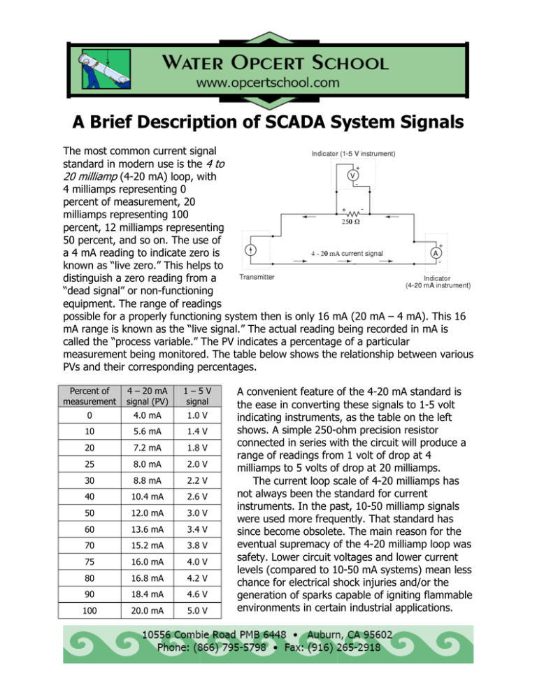
A Brief Description of SCADA System Signals The most common current signal standard in modern use is the 4 to 20 milliamp (4-20 mA) loop, with 4 milliamps representing 0 percent of measurement, 20 milliamps representing 100 percent, 12 milliamps representing 50 percent, and so on. The use of a 4 mA reading to indicate zero is known as “live zero.” This helps to distinguish a zero reading from a “dead signal” or non-functioning equipment. The range of readings possible for a properly functioning system then is only 16 mA (20 mA – 4 mA). This 16 mA range is known as the “live signal.” The actual reading being recorded in mA is called the “process variable.” The PV indicates a percentage of a particular measurement being monitored. The table below shows the relationship between various PVs and their corresponding percentages. Percent of measurement 4 – 20 mA signal (PV) 1–5V signal 0 4.0 mA 1.0 V 10 5.6 mA 1.4 V 20 7.2 mA 1.8 V 25 8.0 mA 2.0 V 30 8.8 mA 2.2 V 40 10.4 mA 2.6 V 50 12.0 mA 3.0 V 60 13.6 mA 3.4 V 70 15.2 mA 3.8 V 75 16.0 mA 4.0 V 80 16.8 mA 4.2 V 90 18.4 mA 4.6 V 100 20.0 mA 5.0 V A convenient feature of the 4-20 mA standard is the ease in converting these signals to 1-5 volt indicating instruments, as the table on the left shows. A simple 250-ohm precision resistor connected in series with the circuit will produce a range of readings from 1 volt of drop at 4 milliamps to 5 volts of drop at 20 milliamps. The current loop scale of 4-20 milliamps has not always been the standard for current instruments. In the past, 10-50 milliamp signals were used more frequently. That standard has since become obsolete. The main reason for the eventual supremacy of the 4-20 milliamp loop was safety. Lower circuit voltages and lower current levels (compared to 10-50 mA systems) mean less chance for electrical shock injuries and/or the generation of sparks capable of igniting flammable environments in certain industrial applications. An Overview of SCADA Signal Calculations DEFINITION OF TERMS Dead signal: A reading from a non-functioning system that can be mistaken for a measurement. Live signal: The range of possible process variables. In a 4 – 20 mA system, any signal below 4 mA or above 20 mA indicates malfunctioning equipment. The range of useable signals is between 4 & 20 mA. Therefore, the live signal = 16 mA. Live zero: A reading other than zero used to indicate zero so that a zero reading can be distinguished from a dead signal. In 4 – 20 mA systems, the live zero = 4 mA. PV: Process variable. The signal reading, in mA, that represents a percentage of a particular measurement. One of the more common uses for SCADA systems is the monitoring of storage levels. Formulas for making these calculations include: PV, mA ⎡ ⎛ Water level, ft = ⎢ ⎜⎜ ⎣ ⎝ Tank SWH, ft ⎛ Water level, ft = ⎜⎜ ⎝ ⎤ ⎞ ⎟⎟ × Live signal, mA ⎥ + Live zero, mA ⎠ ⎦ PV, mA − Live zero, mA ⎞ ⎟⎟ × Tank SWH, ft Live signal, mA ⎠ So, given a SWH of 30 ft, and board reading of 14.67 mA, the water level would be calculated as follows: ⎛ PV, mA − Live zero, mA ⎞ ⎟⎟ × Tank SWH, ft Water level, ft = ⎜⎜ Live signal, mA ⎠ ⎝ ⎛ 14.67 mA − 4.0 mA ⎞ ⎟⎟ × 30 ft = ⎜⎜ 16 mA ⎠ ⎝ ⎛ 10.67 mA ⎞ ⎟⎟ × 30 ft = ⎜⎜ ⎝ 16 mA ⎠ = 0.67 × 30 ft = 20 ft


