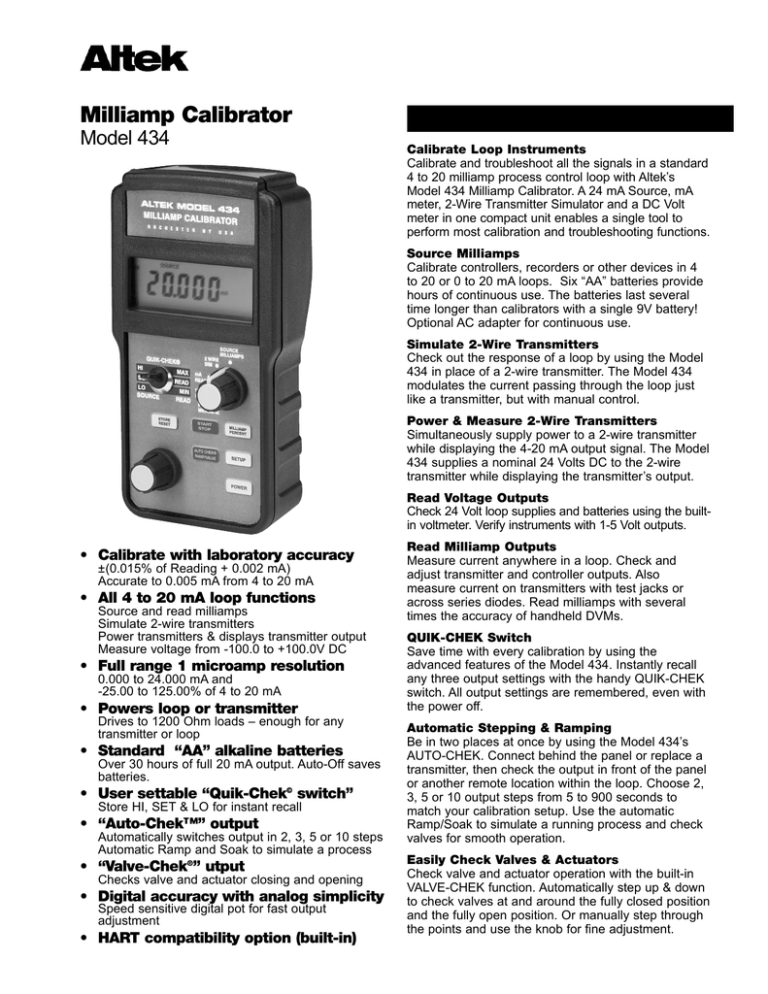
Milliamp Calibrator
Model 434
General description
Calibrate Loop Instruments
Calibrate and troubleshoot all the signals in a standard
4 to 20 milliamp process control loop with Altek’s
Model 434 Milliamp Calibrator. A 24 mA Source, mA
meter, 2-Wire Transmitter Simulator and a DC Volt
meter in one compact unit enables a single tool to
perform most calibration and troubleshooting functions.
Source Milliamps
Calibrate controllers, recorders or other devices in 4
to 20 or 0 to 20 mA loops. Six “AA” batteries provide
hours of continuous use. The batteries last several
time longer than calibrators with a single 9V battery!
Optional AC adapter for continuous use.
Simulate 2-Wire Transmitters
Check out the response of a loop by using the Model
434 in place of a 2-wire transmitter. The Model 434
modulates the current passing through the loop just
like a transmitter, but with manual control.
Power & Measure 2-Wire Transmitters
Simultaneously supply power to a 2-wire transmitter
while displaying the 4-20 mA output signal. The Model
434 supplies a nominal 24 Volts DC to the 2-wire
transmitter while displaying the transmitter’s output.
Read Voltage Outputs
Check 24 Volt loop supplies and batteries using the builtin voltmeter. Verify instruments with 1-5 Volt outputs.
• Calibrate with laboratory accuracy
±(0.015% of Reading + 0.002 mA)
Accurate to 0.005 mA from 4 to 20 mA
• All 4 to 20 mA loop functions
Source and read milliamps
Simulate 2-wire transmitters
Power transmitters & displays transmitter output
Measure voltage from -100.0 to +100.0V DC
• Full range 1 microamp resolution
0.000 to 24.000 mA and
-25.00 to 125.00% of 4 to 20 mA
• Powers loop or transmitter
Drives to 1200 Ohm loads – enough for any
transmitter or loop
• Standard “AA” alkaline batteries
Over 30 hours of full 20 mA output. Auto-Off saves
batteries.
• User settable “Quik-Chek© switch”
Store HI, SET & LO for instant recall
• “Auto-Chek™” output
Automatically switches output in 2, 3, 5 or 10 steps
Automatic Ramp and Soak to simulate a process
• “Valve-Chek®” utput
Checks valve and actuator closing and opening
• Digital accuracy with analog simplicity
Speed sensitive digital pot for fast output
adjustment
• HART compatibility option (built-in)
Read Milliamp Outputs
Measure current anywhere in a loop. Check and
adjust transmitter and controller outputs. Also
measure current on transmitters with test jacks or
across series diodes. Read milliamps with several
times the accuracy of handheld DVMs.
QUIK-CHEK Switch
Save time with every calibration by using the
advanced features of the Model 434. Instantly recall
any three output settings with the handy QUIK-CHEK
switch. All output settings are remembered, even with
the power off.
Automatic Stepping & Ramping
Be in two places at once by using the Model 434’s
AUTO-CHEK. Connect behind the panel or replace a
transmitter, then check the output in front of the panel
or another remote location within the loop. Choose 2,
3, 5 or 10 output steps from 5 to 900 seconds to
match your calibration setup. Use the automatic
Ramp/Soak to simulate a running process and check
valves for smooth operation.
Easily Check Valves & Actuators
Check valve and actuator operation with the built-in
VALVE-CHEK function. Automatically step up & down
to check valves at and around the fully closed position
and the fully open position. Or manually step through
the points and use the knob for fine adjustment.
Applications
Fast milliamp calibration
Simulating a running process
Calibrate the input of a recorder, computer, valve positioner or any
other milliamp input device using the Model 434 to source
milliamps or to simulate a 2-wire transmitter. The source mode
uses the batteries of the Model 434 to power the loop, or in 2-wire
Simulate mode, uses the power supply in the loop.
Store the milliamp values corresponding to the Span and Zero of
the device being calibrated into the HI and LO Quik-Chek
memories (typically 4.000 and 20.000 mA). Flip the Quik-Chek
switch to the HI or LO position to recall the desired output. Turn the
digital pot up and down and monitor the device being calibrated.
Adjust the Span and Zero of the device being calibrated as
required.
Simulate the ramp and soak or stabilizing time of an active loop
with the easily settable Auto-Ramp of the Model 434. This operates
in source mode using the batteries of the Model 434 to power the
loop, or in 2-wire Simulate mode if the loop has its own power
supply. Select any span by storing the endpoints of the range to be
simulated into the HI and LO Quik-Chek positions. Independently
select the number of seconds for the duration of the ramp and the
duration of the soak to approximate the running process. Press the
START/STOP push-button to toggle the simulation on and off.
Calibrating a 2-wire transmitter
Simplify the calibration of 2-wire transmitters by using the Power
Measure mode of the Model 434. In this mode, the Model 434 uses
its internal batteries (or optional AC adapter) to provide the voltage
to power up the 2-wire transmitter.
Connect a sensor or calibrator to the input of the transmitter and
the Model 434 to the output of the transmitter. The display of the
Model 434 will indicate the output of the transmitter in milliamps or
percent, corresponding to the input signal provided by the sensor
or calibrator connected to the input of the transmitter.
Save time obtaining “As Found” and “As Left”
To quickly obtain “As Found” and “As Left” calibration data, use the
Model 434’s Auto-Chek to automatically output steps matching the
input of the instrument being checked. Choose steps of 10, 25, 50
or 100% percent of range, corresponding to ten, five, three or two
equally spaced steps to cover the range between the values stored
in the HI and LO Quik-Chek memories. Select a moderate time
period (10 to 30 seconds) to pause at each step to allow for settling
time of the device being checked. Start the AUTO-CHEK from
either end of the span by setting the Quik-Chek switch in the HI
position, to go from the highest value down or in the LO position, to
start from the lowest value up. Press the START/STOP push-button
to start the AUTO-CHEK and press it again to stop it when you
have recorded all the “As Found” data. Run it in both directions if
you require data to check for hysteresis. Press the START/STOP
push-button to stop the AUTO-CHEK and use the Quik-Chek
switch to toggle between the HI and LO outputs to adjust the Zero
and Span of the instrument being calibrated. Press the
START/STOP push-button again to start the AUTO-CHEK and
record the “As Left” data.
Checking for fully open & fully closed valves
To check a valve & actuator for proper adjustment, you need to
verify that it is fully open or closed with the proper input signal.
Many control systems use a 4 to 20 mA signal to control the
actuator. Checking fully open or closed requires supplying a
milliamp signal that is slightly lower than the exact value, the exact
value at fully open or closed, and a value slightly higher than the
exact value. Check that there is no stem movement in the valve
when the signal changes from out-of-range to the exact value and
that the stem starts to move when the signal is slightly within
range.
The Valve-Chek function of the Model 434 has three ranges
designed to check the fully open & fully closed positions. The
Valve-Chek HI cycles up and down through 19.800, 20.000 and
20.200 mA; the Valve-Chek LO cycles through 3.800, 4.000 and
4.200 mA; and the Valve-Chek SET cycles through 3.800, 4.000,
4.200, 12.000, 19.800, 20.000 and 20.200 mA.
Checking valves for smooth operation
To check that a valve and actuator are operating smoothly, the
valve and actuator must be slowly stroked (opened and closed)
and monitored for rough spots or vibration. The vibration can be felt
by hand, listened to by ear or through a stethoscope.
Set the Auto-Ramp function of the Model 434 to ramp for a number
of seconds (from 5 to 900 seconds) approximating the operating
opening and closing rate of the actuator. Some actuators and
positioners have a slow response time that limits how quickly the
valve can move. This prevents the valve from causing problems
that arise up or down stream when the fluid flow rate changes too
quickly. A few seconds of soak time is needed to give the valve and
positioner time to come to a stop at each end of the ramp.
Press the START/STOP push-button to toggle the Auto-Ramp on
and off. With the Auto-Ramp off, you can use the digital pot to
manually stroke the valve to verify any rough spots.
Locating trip points
Using the 434 as a manual loading station
The Model 434 can assist you in locating the setpoints on
controllers or alarm points on current trips. The Auto-Ramp function
smoothly increases and decreases the output of the 434 to
simulate a running process.
Set the Auto-Ramp to cover the desired span for a moderate time
period (60 seconds, for example). Start the ramp from either end of
the span by setting the Quik-Chek switch in the HI position, to go
from the highest value down or in the LO position, to start from the
lowest value up. Press the START/STOP push-button to start the
ramping and press it again to stop it when the trip point is indicated
on the controller or current trip. The Model 434 will display the
actual value reached when the button was pushed. You can now
turn the digital pot up and down to go back and forth to precisely
determine the trip and reset points.
When you need to keep a stable process running and a controller
or transmitter is going haywire, simply replace the malfunctioning
instrument with the Altek Model 434. The 434 can be used to
substitute for a transmitter signal and regulate the current in the
loop or in place of a controller to supply the signal to drive the
valve or other final control element.
Connect the Model 434 in place of the instrument being serviced
while monitoring and adjusting the signal manually. When the faulty
instrument is repaired, remove the 434 and bring the loop back on
automatic control. Note: be sure to disable the Auto-Off battery
saver if you need to leave the Model 434 on for more than 30
minutes.
Loop and process monitoring (Min/Max)
Automatically verify the control band of a controller or the variability
of a process by using the Model 434 to monitor a milliamp signal.
Set the Model 434 to read mA or % in series with the loop to be
monitored. Let the loop run under normal operating conditions and
flip the Quik-Chek switch to MIN or MAX to instantly recall the
lowest and highest values milliamp signals.
Note: be sure to disable the Auto-Off battery saver if you need to
leave the Model 434 on for more than 30 minutes. Note: flip the
Quik-Switch switch up and down to restart the Auto-Off’s timer for
another 30 minutes.
General instructions
Turn-on
POWER
Turn-off
Each time you turn on the Model 434 the LCD will
display all segments for about 1 second. It then
displays the most recently selected scaling for the
function selected by the selector knob.
POWER
Press the POWER push-button to turn the 434 off. If
AUTO-OFF is enabled the 434 will turn itself off
after 30 minutes of inactivity.
Autocal
SOURCE - The three QUIK-CHEK outputs will be
the same as previously stored. The same three
QUIK-CHEKs are used for the SOURCE & 2 WIRE
SIM functions.
CAL
READ - The 434 is ready to measure milliamps or
DC Volts and is automatically updating the MAX &
MIN readings for recall at any time.
Changing batteries
Low battery is indicated by BAT on the display.
Approximately four hours of operation remain before
the LCD blanks and Model 434 shuts itself down.
Turn the 434 off, loosen the captive screw securing
the battery compartment and lift off the cover from
the bottom of the case. The six “AA” batteries are
easily removed and replaced (alkaline supplied and
recommended). Replace the battery compartment
cover by inserting the tabs and tightening the screw.
Choosing Milliamp or Percent
MILLIAMP
PERCENT
To maintain accuracy, the Model 434 periodically
recalibrates its measuring circuitry against internal
references. While this is occurring the word CAL will
appear on the display for less than 2 seconds.
You may choose to display from 0.000 to 24.000
mA or -25.00 to 125.00%. Press the MILLIAMP /
PERCENT push-button to toggle the display. When
scaled in percent, 100.00% corresponds to 20.000
mA and 0.00% corresponds to 4.000 mA.
Source milliamps and simulate 2-wire transmitters
Select source by turning the selector knob to
SOURCE MILLIAMPS or 2 WIRE SIM and the
letters mA and SOURCE or mA, 2-WIRE SIM and
SOURCE will appear on the LCD display. If percent
4-20 was selected the last time the 434 was used
the indicator % will also appear and the display will
be scaled in percent. To change the output value,
turn the speed sensitive digital pot. Turning the knob
slowly will cause a gradual change in the output. A
faster rate of change will occur when the knob is
turned faster. This function operates in all three
output positions (HI, SET & LO).
Recalling Quik-Chek outputs
HI
SET
LO
SOURCE
SET
LO
SOURCE
STORE
RESET
Note: The same value is stored for both mA and %.
The recalled value will be displayed in the units you
have selected.
Open Loops
The digits on the LCD will flash if there is an open
loop. The word POLARITY will appear on the LCD if
the polarity is reversed in 2-Wire SIM and Read
Transmitter Test Jack modes. Check all the
connections in the loop or try reversing the leads.
Storing QUIK-CHEK Outputs
HI
When you need a stored value just flip the QUIKCHEK switch. Any value for the selected range may
be stored in HI & LO. The Model 434 remembers
the HI, LO and SET values with the power on or off.
1) Switch to HI or LO
2) Turn the knob to desired value
3) Press the STORE push-button
The LCD will flash once to show that the value
was saved
If a value is in the SET position and you want that
value stored in HI or LO, press and hold the STORE
push-button while moving the switch to HI or LO.
The display will flash once to indicate the value has
been stored. Then release the STORE push-button.
Read milliamps
Select read by turning the selector knob to mA
READ OR VDC READ and the letters mA and
READ or V and READ will appear on the LCD
display. If percent 4-20 was selected the last time
the 434 was used the indicator % will also appear
and the display will be scaled in percent. There are
two modes for mA READ. The first mode is used to
read the current flowing through a loop or when
measuring the output of a controller. The second
mode has a fuse for protection and is used to
measure the current on transmitter test jacks or
across a diode in series with the loop.
MIN/MAX
To read the Maximum or Minimum INPUT since
READ mode was entered, simply switch to MAX or
MAX MIN. The value will appear on the LCD along with
READ the word MAX or MIN. The MAX/MIN values are
MIN automatically updated and may be viewed at any
READ time without disturbing the other values.
Restarting MIN/MAX
STORE
RESET
Pressing the STORE/RESET push-button will cause
the Model 434 to store the present reading into the
MAX and MIN memories. Upon releasing the
STORE/RESET push-button the 434 will resume
reading the input and update the MAX & MIN values
as the measured signal changes.
Out of range signals
Signals above or below those available for the
currently selected range will be indicated by Or and
Ur on the display. The word POLARITY will appear
on the LCD if the polarity is reversed in Read
Transmitter Test Jack mode.
Source milliamps
mA, mA % (Percent of 4 to 20 mA)
Choose this function to provide an output from 0.000 to 24.000 mA. The
compliance voltage is a nominal 24 VDC to provide the driving power to
your milliamp receivers or to drive a whole loop.
1) Disconnect one or both input wires from the device to be calibrated.
2) Press the POWER push-button to turn the Model 434 on and turn the
selector knob to SOURCE MILLIAMPS.
3) Connect the red SOURCE lead of the calibrator to the plus (+) input
of the device and the black SOURCE lead to the minus (-).
4) Press the MILLIAMP/PERCENT push-button to toggle the display
between indicating 0.000 to 24.000 mA and -25.00 to 125.00% of 4
to 20 mA. The words SOURCE and mA or SOURCE, mA and % are
displayed.
MILLIAMP CALIBRATOR
Milliamp Receiver Input
Controller
Transmitter
Computer
Logger
I/P
DCS
SOURCE
MILLIAMPS
2 WIRE
SIM
QUIK-CHEK
HI
MAX
SET
READ
LO
SOURCE
MIN
READ
VDC
READ
POWER
MEASURE
START
STOP
STORE
RESET
Continuously adjust the output by turning the speed sensitive digital pot.
Zero & Span (or any other values) are available by using the LO and HI
"QUIK-CHEKs" to recall your stored settings (4.000 & 20.000 mA
defaults).
mA
READ
AUTO CHEK
RAMP / VALVE
MILLIAMP
PERCENT
SETUP
POWER
Simulate 2-wire transmitters
2-WIRE SIM mA, 2-WIRE SIM % (Percent 4 to 20mA)
Choose this function to simulate a 2-wire transmitter output from 1.00 to
24.00 mA. Operates in loops with power supply voltages from 3 to 45
VDC.
MILLIAMP CALIBRATOR
1) Disconnect existing 2-wire Transmitter from the loop
2) Press the POWER push-button to turn the Model 434 on and turn the
selector knob to 2 WIRE SIM.
2) Connect the red SOURCE lead of the calibrator to the plus (+) input
of the field connections and the black SOURCE lead to the minus (-)
3) Press the MILLIAMP/PERCENT push-button to toggle the display
between indicating 0.000 to 24.000 mA and -25.00 to 125.00% of 4
to 20 mA. The words SOURCE, 2-WIRE SIM and mA or SOURCE,
2-WIRE SIM, mA and % are displayed.
Receiver
(Powers external
2-Wire Transmitter)
SOURCE
MILLIAMPS
2 WIRE
SIM
QUIK-CHEK
HI
MAX
SET
READ
LO
SOURCE
MIN
READ
STORE
RESET
Continuously adjust the output by turning the speed sensitive digital pot.
Zero & Span (or any other values) are available by using the LO and HI
"QUIK-CHEKs" to recall your stored settings (4.000 & 20.000 mA
defaults).
mA
READ
VDC
READ
POWER
MEASURE
START
STOP
MILLIAMP
PERCENT
AUTO CHEK
RAMP / VALVE
SETUP
POWER
To
Sensor
+IN-
REF +OUT-
Typical
2-Wire
Transmitter
Power Supply
2 to 45 VDC
(Disconnected)
Power & measure 2-wire transmitters
PWR XMTR mA, PWR XMTR %
Choose this function to simultaneously supply power to a 2-wire
transmitter while displaying the 4-20 mA output of the transmitter.
1) Disconnect one or both input wires from the 2-wire transmitter to be
calibrated.
2) Press the POWER push-button to turn the Model 434 on and turn the
selector knob to POWER MEASURE.
3) Connect the red SOURCE lead of the calibrator to the plus (+) input
of the device and the black SOURCE lead to the minus (-).
4) Connect an appropriate sensor or calibrator to the input of the 2-wire
Transmitter.
3) Press the MILLIAMP/PERCENT push-button to toggle the display
between indicating 0.000 to 24.000 mA and -25.00 to 125.00% of 4
to 20 mA. The words SOURCE, PWR XMTR and mA or SOURCE,
PWR XMTR, mA and % are displayed.
The Model 434 supplies a nominal 24 Volts DC at 24 mA to power the 2wire transmitter. The current passed by the transmitter will be accurately
displayed by the 434. Calibrate the transmitter in the usual manner and
disconnect the 434.
HART COMMUNICATOR COMPATIBILITY
An internal jumper enables the Power & Measure 2-wire transmitter
mode to be compatible with HART communicators and transmitters. This
eliminates the need to add an external load resistor when
communicating with a HART transmitter (refer to diagram on page 7).
Transmitter Input
Sensor
Process Signal
Simulated Input
MILLIAMP CALIBRATOR
+OUT-
REF
+IN-
SOURCE
MILLIAMPS
2 WIRE
SIM
QUIK-CHEK
HI
MAX
SET
READ
LO
SOURCE
MIN
READ
STORE
RESET
Typical
2-Wire
Transmitter
mA
READ
VDC
READ
POWER
MEASURE
START
STOP
AUTO CHEK
RAMP / VALVE
MILLIAMP
PERCENT
SETUP
POWER
Read milliamps
mA, mA % (Percent of 4 to 20 mA)
Choose this function to measure loop current or controller outputs from
0.000 to 24.000 mA or -25.00 to 125.00%.
1) Open the current loop at any convenient point along the signal path
2) Press the POWER push-button to turn the Model 434 on and turn the
selector knob to READ MILLIAMPS.
3) If the diode symbol
appears on the display press the SETUP
push-button and only READ and mA or READ, mA and % are
displayed.
4) Press the MILLIAMP/PERCENT push-button to toggle the display
between indicating 0.000 to 24.000 mA and -25.00 to 125.00% of 4
to 20 mA. The words READ and mA or READ, mA and % are
displayed.
5) Connect the red (+) lead of the calibrator to the more positive point of
the break and the black (-) lead to the more negative.
MILLIAMP CALIBRATOR
Milliamp Output Signal
Controller
Transmitter
P/I
DCS
SOURCE
MILLIAMPS
2 WIRE
SIM
QUIK-CHEK
MAX
HI
SET
READ
LO
SOURCE
MIN
READ
Display the present reading, Maximum or Minimum by moving the toggle
switch from READ to MAX or MIN. If the Model 434 is connected in the
wrong polarity, the word POLARITY will appear in the display. Simply
reverse the leads for correct indication.
mA
READ
VDC
READ
POWER
MEASURE
MILLIAMP
PERCENT
START
STOP
STORE
RESET
AUTO CHEK
RAMP / VALVE
SETUP
POWER
Read transmitter test jacks or across loop diodes
mA, mA % (Percent of 4 to 20 mA)
Choose this function to measure loop current on transmitter test jacks or
across diodes in series with the milliamp loop. Display from 0.000 to
24.000 milliamps or -25.00 to 125.00%. The read transmitter test jack
function has a fuse for protection.
1) Press the POWER push-button to turn the Model 434 on and turn the
selector knob to READ MILLIAMPS.
2) If the diode symbol doesn’t appear press the SETUP push-button
until The words READ, mA and the diode symbol
or READ, mA,
% and the diode symbol
are displayed.
3) Press the MILLIAMP/PERCENT push-button to toggle the display
between indicating 0.000 to 24.000 mA and -25.00 to 125.00% of 4
to 20 mA. The words READ, mA and the diode symbol
or READ,
mA, % and the diode symbol
are displayed.
4) Connect the red (+) lead of the calibrator to the more positive point of
the break and the black (-) lead to the more negative.
MILLIAMP CALIBRATOR
+ TEST
- POINTS
SOURCE
MILLIAMPS
2 WIRE
SIM
QUIK-CHEK
MAX
HI
mA
READ
READ
SET
VDC
READ
MIN
READ
LO
SOURCE
POWER
MEASURE
START
STOP
STORE
RESET
AUTO CHEK
RAMP / VALVE
Display the present reading, Maximum or Minimum by moving the toggle
switch from READ to MAX or MIN. If the Model 434 is connected in the
wrong polarity, the word POLARITY will appear in the display. Simply
reverse the leads for correct indication.
MILLIAMP
PERCENT
SETUP
POWER
Power & measure 2-wire transmitters
V DC
Choose this function to measure from -99.99 to +99.99 Volts DC to
check batteries, loop power supplies or any process voltage output.
1) Press the POWER push-button to turn the Model 434 on and turn the
selector knob to VDC READ.
2) Connect the red (+) lead of the calibrator to the positive point and the
black (-) lead to the negative.
Display the present reading, Maximum or Minimum by moving the toggle
switch from READ to MAX or MIN. If the Model 434 is connected in the
wrong polarity, the word POLARITY will appear in the display. Simply
reverse the leads for correct indication.
MILLIAMP CALIBRATOR
Voltage Output Signal
Controller
Transmitter
Power Supply
SOURCE
MILLIAMPS
2 WIRE
SIM
QUIK-CHEK
MAX
HI
READ
SET
LO
SOURCE
STORE
RESET
MIN
READ
mA
READ
VDC
READ
POWER
MEASURE
START
STOP
AUTO CHEK
RAMP / VALVE
MILLIAMP
PERCENT
SETUP
POWER
Automatic functions
There are three automatic functions - Auto-Chek, Ramp & ValveChek. These automatic functions operate in the SOURCE
MILLIAMPS and 2 WIRE SIM modes. Each automatic function is
quickly selected and indicated on the LCD. All automatic operation
are configurable and the configurations are remembered even
when the power is off. Whenever an automatic function is
selected, the previous configuration is recalled and
the function will be indicated on the LCD. When no automatic
functions are indicated on the LCD, all automatic functions are off.
Auto-Chek
The Model 434 can be set up to automatically or manually step
the output with your choice of 2, 3, 5 or 10 steps from Zero to Full
Scale. Select automatic steps from 5 to 900 seconds or select 0
seconds to manually select each of the 2, 3, 5 or 10 steps.
Ramp
Choose the ramp setting to repeatedly ramp between adjustable
Zero and Full Scale. You select the ramp time from 5 to 900 and
soak tome from 0 to 900 seconds. The Model 434 will smoothly
ramp the output and automatically hold steady at each end if you
would like time to adjust the device being calibrated. The ramp
can also be set up for a narrower span to simulate the ramping &
soaking of a running process loop.
Valve-Chek
Check your valves and actuators for proper operation with
automatic or manual steps. Fixed settings of 3.800, 4.000 and
4.200 mA check the low end of the actuator and fixed settings of
19.800, 20.000 and 20.200 mA check the high end. The 434 can
also be setup to automatically or manually step through both high
and low fixed settings with the addition of a midpoint at 12.000 mA.
Auto-Chek
Setup
Automatic stepping (5 to 900 second per step)
1) Select SOURCE MILLIAMPS or 2 WIRE SIM
2) Press the AUTO CHEK RAMP/VALVE push-button until AUTOCHEK appears on the LCD.
3) Press the SETUP push-button and the words AUTO-CHEK,
STEP and % appear on the LCD prompting you to enter the
percent of span change between steps. Turn the knob until the
correct percentage appears on the LCD. For 2 steps choose
100%, 3 steps choose 50%, 5 steps choose 25% and for 10
steps choose 10%. Press the SETUP push-button to continue.
4) The words AUTO-CHEK, STEP and SEC appear on the display
prompting you to enter the number of seconds between steps.
Turn the knob until the correct number of seconds per step
(from 5 to 900) appears on the LCD. If you would like manual
operation instead of automatic operation select 0 seconds per
step. Press the SETUP push-button to complete the AutoChek setup.
5) Store the desired Full Scale & Zero into the HI & LO Quik-Chek
positions.
1) Press the START/STOP push-button to automatically step the
output up and down. The word STEP will flash on the LCD
and the output will automatically step after the number of
seconds selected in the setup have elapsed.
2) Press the START/STOP push-button to stop the automatic
stepping. Press it again will restart.
Note: The Automatic stepping may be restarted at the HI or LO
stored values based on the position of the Quik-Chek switch. The
Auto-Chek will begin at the value stored in LO if the Quik-Chek
switch is in the LO position or will begin at the value stored in HI if
the Quik-Chek switch is in the HI position. The Auto-Chek will
begin at the last automatic step if the Quik-Chek is in the SET
position.
Manual Stepping (0 seconds per step)
Press the START/STOP push-button to manually step the output up
and down. The output will step through the number of steps setup
between the values stored in the HI & LO Quik-Chek positions each
time you press the pushbutton. You may turn the knob at any time to
Valve-Chek
Setup
Manual operation (0 seconds per step)
1) Select SOURCE MILLIAMPS or 2 WIRE SIM
2) Press the AUTO CHEK RAMP/VALVE push-button until
VALVE-CHEK appears on the LCD.
3) Press the SETUP push-button and the words VALVE-CHEK,
STEP and SEC appear on the display prompting you to enter
the number of seconds between steps. Turn the knob until the
correct number of seconds per step (from 5 to 900) appears on
the LCD. If you would like manual operation instead of
automatic operation select 0 seconds per step. Press the
SETUP push-button to complete the Auto-Chek setup.
Press the START/STOP push-button to manually step the output
up and down. The output will step between the values in the
Valve-Chek range selected by the position of the Quik-Chek
switch each time you press the START/STOP push-button. You
may turn the knob at any time to precisely adjust the output, find a
trip point or alarm, or stroke a valve.
Automatic stepping (5 to 900 second per step)
1) Press the START/STOP push-button to automatically step the
output up and down. The word STEP will flash on the LCD and
the output will automatically step after the number of seconds
selected in the setup have elapsed.
2) Press the START/STOP push-button to stop the automatic
stepping. Press it again to restart.
Note: Whenever Valve-Chek is activated the Quik-Chek HI & LO
memories are reset to 20.000 and 4.000 mA.
Valve-Chek ranges
Valve-Chek HI
Cycles up and down through 19.800, 20.000, 20.200 mA
Valve-Chek LO
Cycles up and down through 3.800, 4.000, 4.200 mA
Valve-Chek LO/HI
Cycles up and down among 3.800, 4.000, 4.200, 12.000,
19.800, 20.000, 20.200 mA
The selection of the Valve-Chek range is based on the position of
the Quik-Chek switch. If the Quik-Chek switch is in the HI position
the Valve-Chek HI range is selected, If the Quik-Chek switch is in
the LO position the Valve-Chek LO range is selected and if the
Quik-Chek switch is in the SET position the Valve-Chek LO/HI
range is selected.
Ramp
Setup
Automatic Operation
1) Select SOURCE MILLIAMPS or 2 WIRE SIM
2) Press the AUTO CHEK RAMP/VALVE push-button until RAMP
appears on the LCD.
3) Press the SETUP push-button and the words AUTO-CHEK,
RAMP and SEC appear on the display prompting you to enter
the number of seconds between steps. Turn the knob until the
correct number of seconds per ramp (from 5 to 900) appears
on the LCD. Press the SETUP push-button to continue.
4) The words AUTO-CHEK, RAMP, SOAK and SEC appear on
the display prompting you to enter the number of seconds to
hold the output steady at the top and bottom of each ramp
cycle. Turn the knob until the correct number of seconds to
hold at each end (0 for no hold or from 1 to 900) appears on
the LCD. Press the SETUP push-button to complete the AutoChek setup.
5) Store the required Span & Zero into the HI & LO Quik-Chek
positions.
1) Press the START/STOP push-button to automatically ramp the
output up and down. The word RAMP will flash on the LCD
and the output will automatically ramp after the number of
seconds selected in the setup have elapsed. The output will
hold steady at the top and bottom of each ramp cycle for the
number of seconds selected for the SOAK time. If the the soak
time is set for 0 seconds the output will continuously ramp
without holding at the top and bottom.
2) Press the START/STOP push-button to stop the automatic
ramping. Press it again to restart.
Note: The Automatic ramp may be restarted at the HI or LO
stored values based on the position of the Quik-Chek switch.
The Auto-Chek will begin at the value stored in LO if the QuikChek switch is in the LO position or will begin at the value
stored in HI if the Quik-Chek switch is in the HI position. The
Auto-Chek will begin at the last value selected if the Quik-Chek
is in the SET position.
Returning to manual operation
Press the AUTO CHEK/AUTO VALVE push-button until no
automatic modes are selected. This is indicated when none of the
automatic modes (AUTO-CHEK, AUTO-VALVE or RAMP) are
shown on the LCD
General operations
HART Compatibility
Auto-Off
An internal jumper enables the Power & Measure 2 Wire
Transmitter mode to be compatible with HART communicators and
transmitters. By removing this jumper a 250 ohm resistor is placed
in series with the output of the Model 434. This internal resistor
eliminates the need to add an external load resistor when
communicating with a HART transmitter (refer to diagram below).
This reduces the typical drive capability to 950 ohms.
Model 434 can be set up to turn itself off after 30 minutes of
inactivity. The internal timer is reset to 30 minutes each time a
pushbutton is pressed. This configuration is part of the DEFAULT
SETTINGS below.
Fuse Replacement
If the Model 434 no longer meaures current between transmitter
test jacks or across a diode the internal fuse may have blown.
Replace it with a fuse 5 x 20 mm and rated to 250 mA at 250V.
Refer to the diagram below for location.
Disconnect unit from circuit before changing fuse or
HART jumper.
Accessing the Jumper & Fuse
1) Turn the 434 off
2) Loosen the screw on the battery cover. Remove the cover and
batteries.
3) Remove the four remaining screws and carefully separate the
enclosure.
4) Refer to the diagram for jumper location or fuse replacement.
5) Reverse the procedure for reassembly.
HART
Disabled*
HART
Enabled
Fuse, 5x20mm
250 mA, 250V
CAL
250 OHM
ENABLE
(HART)
Do Not
Change
Position
Default settings - user options
The Model 434 may be restored to the factory settings. This will
reset the HI and LO “QUIK-CHEK” memories to 20.000 mA and
4.000 mA and the SET memory to midrange (12.000 mA). Prompts
guide you for selection of AUTO-OFF.
1) Press and hold the STORE/RESET push-button while turning
the 434 on.
2) Keep pressing the STORE/RESET push-button until the display
flashes (about 5 seconds) then release.
3) The words BAT and ON will appear on the display indicating
that AUTO-OFF is selected.
4) To toggle the AUTO-OFF function on and off press the SETUP
push-button and the words oN and oFF will display.
5) After five seconds the 434 will automatically store your choice
and the 434 will begin normal operation. Or you may press the
STORE/RESET push-button to accept your choice and begin
operation.
Tilt Stand and Carrying Case
The Model 434 comes with a carrying case and a built-in tilt
stand/hanger. The 434 is held securely in the case by VELCRO®.
The tilt stand is easily raised by pulling the stand until it locks into
place. The stand can also be reversed for use as a hanger to
suspend the Model 434.
*Factory
Default
VELCRO® is a registered trademark of Velcro USA
Specifications
(Unless otherwise indicated, specifications are for one year in ±% of
span at 23ºC)
General
Milliamp accuracy: ±(0.015% of Reading + 0.002 mA)
Temperature effect: ±0.008%/°C based on 23°C ±25°C
Batteries: Six "AA" batteries (Alkaline supplied and recommended)
Battery life:
Milliamp Source & 2-wire Modes: Nominal 44 hours
at 12 mA, 30 hours at 20 mA into 250 Ohm load
Other Functions: Nominal 75 hours
AC Adapters: Optional, 120 or 240 VAC, 50/60 Hz
Low battery indication: "BAT" indication on the display at 6.5 V
nominal, approximately 4 hours left
Operating temperature range: -5 to +130°F (-20 to +55°C)
Storage temperature range: -13 to +130°F (-25 to +55°C)
Relative humidity: 10 to 90%, non-condensing for 24 hours
Warm up time: 10 seconds to rated accuracy, 2 minutes to full
accuracy
Overall size: 6.23 x 3.27 x 1.94 inches (158.1 x 83.1x 49.3 mm)
Weight: 1lb, 2oz (0.5 kg)
Milliamp source
Ranges:
0.000 to 24.000mA with 1 microamp resolution
-25.00 to 125.00% of 4-20mA with 0.01% resolution
Typical drive capability: 1200 Ohms @ 20.000 mA
Power to drive receiver: Nominal 24 VDC
Compliance voltage:
0 to 500 Ohm Load: 12 V nominal @ 20.000 mA
500 to 1200 Ohm load: 24 V nominal @ 20.000 mA
Power & measure 2-wire transmitters
Ranges: Same as Milliamp Source
Output current: up to 24.000 mA
Typical drive capability: 1200 Ohms @ 20.000 mA
Power to external 2-wire transmitter: Nominal 24 VDC
Read milliamps
Ranges: Same as Milliamp Source
Voltage burden: 0.9 V at 4 mA, 1.2 V at 20 mA,1.4 V at 24 mA
Read transmitter test jacks or
across loop diodes
Ranges: Same as Milliamp Source
OvervoltagepProtection: Fuse, 5 x 20 mm, 250 mA, 250 V
Input impedance: 15 Ohms
Simulate 2-wire transmitters
Ranges: 1.000 to 24.000 mA
Loop voltage limits: Minimum, 2 VDC; Maximum 50 VDC
Measure DC Volts
Range: -100.0 to +100.0 DC Volts
Accuracy: ±0.5% of Full Scale Reading from 0.0 to 100.0V
Input resistance: > 1 Meg Ohm
Source resistance effect: 0.01% per 100 Ohms
Ranges and accuracy
Milliamp Source, Power & Measure 2-wire
Transmitters, Read Milliamps, Read Transmitter Test
Jacks. Simulate 2-wire Transmitters operates from
1.000 to 24.000 mA.
Milliamp
Low
Hi
Functions
Limit
Limit
24.000 mA
23.994 mA
24.006 mA
20.000
19.995
20.005
12.000
11.996
12.004
4.000
3.997
4.003
1.000
0.998
1.002
0.000
-0.002
0.002
Measure DC Volts
Read
DC Volts
100.0 V
50.0
25.0
5.0
0.0
Low
Limit
99.5 V
49.5
24.5
4.5
-0.5
Hi
Limit
100.5 V
50.5
25.5
5.5
0.5
Warranty
Altek products are warranted to be free from defects
in material and workmanship (excluding fuses,
batteries and leads) for a period of three years from
the date of shipment. Warranty repairs can be
obtained by returning the equipment prepaid to our
factory. Products will be replaced, repaired, or
adjusted at our option. Altek gives no other
warranties, including any implied warranty of fitness
for a particular purpose. Also, Altek shall not be liable
for any special, indirect, incidental or consequential
damages or losses arising from the sale or use of its
products.
Altek Industries, Inc.
PO Box 1106, Everett, WA 98206
1520 75th Street SW, Everett, WA 98203
For more information:
U.S.A. (800) 322-5835
Fax (800) 265-6340
Service fax (425) 446-6331
E-mail: sales@altekcalibrators.com
Web: www.altekcalibrators.com
PN 1886512 Rev B December 2002
©2002 Altek Industries, Inc. Specifications subject to change without notice.
All rights reserved. Printed in U.S.A.

