Refrigerant pipes calculation
advertisement

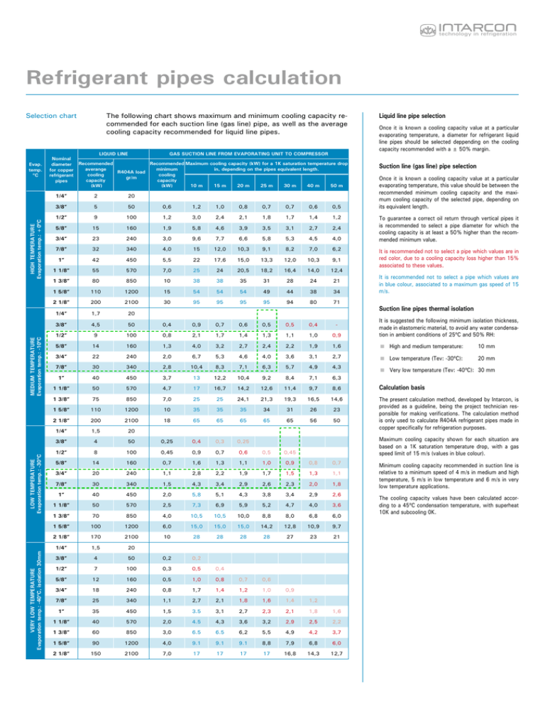
technology in refrigeration Refrigerant pipes calculation The following chart shows maximum and minimum cooling capacity recommended for each suction line (gas line) pipe, as well as the average cooling capacity recommended for liquid line pipes. Selection chart VERY LOW TEMPERATURE Evaporation temp.: -40ºC, isolation 30mm LOW TEMPERATURE Evaporation temp.: -30ºC MEDIUM TEMPERATURE Evaporation temp.: -10ºC HIGH TEMPERATURE Evaporation temp.: +0ºC Evap. temp. ºC 56 Nominal diameter for copper refrigerant pipes LIQUID LINE GAS SUCTION LINE FROM EVAPORATING UNIT TO COMPRESSOR Recommended Recommended Maximum cooling capacity (kW) for a 1K saturation temperature drop averange minimum in, depending on the pipes equivalent length. R404A load cooling cooling gr/m capacity capacity 10 m 15 m 20 m 25 m 30 m 40 m 50 m (kW) (kW) 1/4” 2 3/8” 5 20 50 0,6 1,2 1,0 0,8 0,7 0,7 0,6 0,5 1/2” 9 100 1,2 3,0 2,4 2,1 1,8 1,7 1,4 1,2 5/8” 15 160 1,9 5,8 4,6 3,9 3,5 3,1 2,7 2,4 3/4” 23 240 3,0 9,6 7,7 6,6 5,8 5,3 4,5 4,0 7/8” 32 340 4,0 15 12,0 10,3 9,1 8,2 7,0 6,2 1” 42 450 5,5 22 17,6 15,0 13,3 12,0 10,3 9,1 1 1/8” 55 570 7,0 25 24 20,5 18,2 16,4 14,0 12,4 1 3/8” 80 850 10 38 38 35 31 28 24 21 1 5/8” 110 1200 15 54 54 54 49 44 38 34 2 1/8” 200 2100 30 95 95 95 95 94 80 71 1/4” 1,7 20 3/8” 4,5 50 0,4 0,9 0,7 0,6 0,5 0,5 0,4 - Liquid line pipe selection Once it is known a cooling capacity value at a particular evaporating temperature, a diameter for refrigerant liquid line pipes should be selected deppending on the cooling capacity recommended with a ± 50% margin. Suction line (gas line) pipe selection Once it is known a cooling capacity value at a particular evaporating temperature, this value should be between the recommended minimum cooling capacity and the maximum cooling capacity of the selected pipe, depending on its equivalent length. To guarantee a correct oil return through vertical pipes it is recommended to select a pipe diameter for which the cooling capacity is at least a 50% higher than the recommended minimum value. It is recommended not to select a pipe which values are in red color, due to a cooling capacity loss higher than 15% associated to these values. It is recommended not to select a pipe which values are in blue colour, associated to a maximum gas speed of 15 m/s. Suction line pipes thermal isolation 1/2” 9 100 0,8 2,1 1,7 1,4 1,3 1,1 1,0 0,9 It is suggested the following minimum isolation thickness, made in elastomeric material, to avoid any water condensation in ambient conditions of 25ºC and 50% RH: 5/8” 14 160 1,3 4,0 3,2 2,7 2,4 2,2 1,9 1,6 High and medium temperature: 10 mm 3/4” 22 240 2,0 6,7 5,3 4,6 4,0 3,6 3,1 2,7 Low temperature (Tev: -30ºC): 20 mm 7/8” 30 340 2,8 10,4 8,3 7,1 6,3 5,7 4,9 4,3 Very low temperature (Tev: -40ºC): 30 mm 6,3 1” 40 450 3,7 13 12,2 10,4 9,2 8,4 7,1 1 1/8” 50 570 4,7 17 16,7 14,2 12,6 11,4 9,7 8,6 1 3/8” 75 850 7,0 25 25 24,1 21,3 19,3 16,5 14,6 1 5/8” 110 1200 10 35 35 35 34 31 26 23 2 1/8” 200 2100 18 65 65 65 65 65 56 50 1/4” 1,5 20 3/8” 4 50 0,25 0,4 0,3 0,25 Calculation basis The present calculation method, developed by Intarcon, is provided as a guideline, being the project technician responsible for making verifications. The calculation method is only used to calculate R404A refrigerant pipes made in copper specifically for refrigeration purposes. Maximum cooling capacity shown for each situation are based on a 1K saturation temperature drop, with a gas speed limit of 15 m/s (values in blue colour). 1/2” 8 100 0,45 0,9 0,7 0,6 0,5 5/8” 14 160 0,7 1,6 1,3 1,1 1,0 0,45 0,9 0,8 0,7 3/4” 20 240 1,1 2,8 2,2 1,9 1,7 1,5 1,3 1,1 7/8” 30 340 1,5 4,3 3,4 2,9 2,6 2,3 2,0 1,8 1” 40 450 2,0 5,8 5,1 4,3 3,8 3,4 2,9 2,6 1 1/8” 50 570 2,5 7,3 6,9 5,9 5,2 4,7 4,0 3,6 1 3/8” 70 850 4,0 10,5 10,5 10,0 8,8 8,0 6,8 6,0 1 5/8” 100 1200 6,0 15,0 15,0 15,0 14,2 12,8 10,9 9,7 2 1/8” 170 2100 10 28 28 28 28 27 23 21 1/4” 1,5 20 3/8” 4 50 0,2 0,2 0,6 1/2” 7 100 0,3 0,5 5/8” 12 160 0,5 1,0 0,4 0,8 0,7 3/4” 18 240 0,8 1,7 1,4 1,2 1,0 7/8” 25 340 1,1 2,7 2,1 1,8 1,6 1,4 1” 35 450 1,5 3.5 3,1 2,7 2,3 2,1 1,8 1,6 1 1/8” 40 570 2,0 4.5 4,3 3,6 3,2 2,9 2,5 2,2 0,9 1,2 1 3/8” 60 850 3,0 6.5 6.5 6,2 5,5 4,9 4,2 3,7 1 5/8” 90 1200 4,0 9.1 9.1 9.1 8,8 7,9 6,8 6,0 2 1/8” 150 2100 7,0 17 17 17 17 16,8 14,3 12,7 Minimum cooling capacity recommended in suction line is relative to a minimum speed of 4 m/s in medium and high temperature, 5 m/s in low temperature and 6 m/s in very low temperature applications. The cooling capacity values have been calculated according to a 45ºC condensation temperature, with superheat 10K and subcooling 0K. technology in refrigeration Equivalent length The equivalent length of a refrigeration pipe is usually about 1,2 to 5 times longer than its real length, depending on the number of elbows and chokes in it. As a guideline, the values shown in the following chart can be used to get an approximate calculation: Equivalent length (m) Nominal diameter for copper refrigerant pipes 90º elbow T-shape coupler straight flow angular flow Choke Siphon Angular service valve Gate service valve 3/8” 0,7 0,3 0,8 0,3 1,1 1,8 0,2 1/2” 0,8 0,3 0,9 0,4 1,2 2,0 0,2 5/8” 0,9 0,4 1,0 0,5 1,4 2,2 0,3 3/4” 1,0 0,4 1,2 0,6 1,6 2,5 0,3 7/8” 1,1 0,5 1,4 0,6 1,8 3,0 0,3 1” 1,2 0,5 1,5 0,7 2,0 3,5 0,3 1 1/8” 1,4 0,6 1,8 0,8 2,3 4,0 0,4 1 3/8” 1,7 0,7 2,2 1,0 2,7 5,0 0,5 1 5/8” 2,0 0,9 2,7 1,2 3,5 6,0 0,6 2 1/8” 2,5 1,1 3,3 1,5 4,3 8,0 0,7 Recommendations Example 1.- cooling pipes calculation Sizing up cooling pipes to service one evaporating unit of a cooling capacity of 1500W in a -20ºC cold room with DT1 = 7K. We size up the liquid pipes according to recommended cooling capacity, it is acceptable a pipe diameter of 1/4”. We accept as premise a equivalent length of 1,5 times longer than real length. In our situation: Leq = 1,5 x 20 m = 30 m We accept a pressure drop equivalent to a 1K saturation temperature drop, we see in 30m column, in low temperature section (evaporation temp. -30ºC), and we found that: 3/4” pipes are related to a recommended maximum cooling capacity of 1,5 kW, but with a cooling capacity loss higher than 15% (values in red colour). 7/8” pipes are related to a recommended minimum cooling capacity of 1,5 kW, but making difficult the gas return in vertical pipes. It is recommended to take notice of the following tips for a better cooling pipes design: • Designing the pipes as straight as possible, with the lowest number of elbows, couplers and refrigerant jets. So, it is recommended to utilize 7/8” pipes in horizontal and descending piping and 3/4” only in ascending piping. We can check out that equivalent length estimated is right, indeed: Leq = 20m + 3x 1,1m (elbow) + 2x 1,6m (siphon) + + 2,5m (service valve) = 29 m • Installing a siphon in vertical pipes in suction lines every 3 metres. • Giving the horizontal stretch a little inclination down to the compressor. • Connection from the evaporating unit to the suction line collector should be always undertaken from the unit up to the collector. Example 1 Sizing up a multiservice installation pipes, as seen in scheme, to service 5 evaporating unit of 1000W each one in 0ºC cold rooms with DT1 = 8K. We size up the liquid pipes according to recommended cooling capacity, it is acceptable a pipe diameter of 1/4” for a cooling capacity between 1000 and 2000W and a pipe diameter of 3/8” for a cooling capacity between 3000W and 5000W. 5m x 7/8” 3m x 7/8” We accept as premise a equivalent length of 1,5 times longer than real length to the most distant evaporating unit. In our situation: 3m x 3/4” 1/4” 1/4” 3m x 7/8” Example 2.- multiservice installation calculation Siphon every 3 metres in vertical pipes 1/4” 3m x 3/4” 1/4” We accept a pressure drop equivalent to a 2K saturation temperature drop, we see in 25m column (50m÷2), in medium temperature section (evaporation temp. -10ºC), and we found that: For a cooling capacity of 1000W it is recommended a 1/2” pipe, 3m x 7/8” Example 2 Leq = 1,5 x 35 m = 52,5 m of 2000W it is recommended a 5/8” pipe, 1/4” of 3000W it is recommended a 3/4” pipe, 5m x 7/8” and of 5000W it is recommended a 7/8” pipe, We can check out that equivalent length estimated is right, indeed: 1/4” 5m x 1/2” 5m x 5/8” 10m x 7/8” 3/8” 1/4” Leq = 35m+ 1,1m (elbow) + 3x 1,8m + 1,2m (siphons) + +0,5+0,6+0,6 (chokes) + 2,5+0,2 (valves) = 47m 3/8” 1/4” 5m x 3/4” 1/4” 5m x 1/2” 5m x 5/8” 5m x 1/2” 5m x 1/2” 5m x 1/2” 5m x 1/2” 5m x 1/2” 57


