DoorKing Part Numbers
STAND ALONE CARD READER SYSTEM
1524-331
1524-080
card reader only
card reader with lighted enclosure
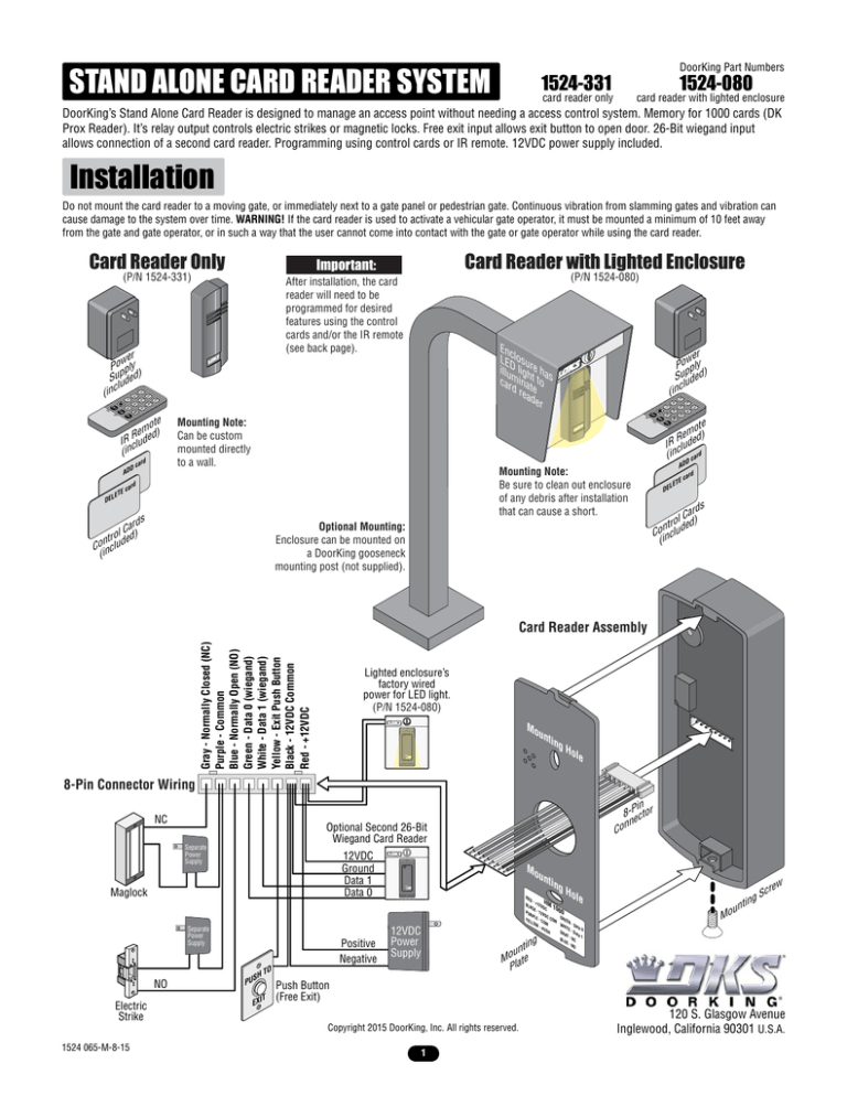
DoorKing’s Stand Alone Card Reader is designed to manage an access point without needing a access control system. Memory for 1000 cards (DK
Prox Reader). It’s relay output controls electric strikes or magnetic locks. Free exit input allows exit button to open door. 26-Bit wiegand input
allows connection of a second card reader. Programming using control cards or IR remote. 12VDC power supply included.
Installation
Do not mount the card reader to a moving gate, or immediately next to a gate panel or pedestrian gate. Continuous vibration from slamming gates and vibration can
cause damage to the system over time. WARNING! If the card reader is used to activate a vehicular gate operator, it must be mounted a minimum of 10 feet away
from the gate and gate operator, or in such a way that the user cannot come into contact with the gate or gate operator while using the card reader.
Card Reader Only
Important:
Card Reader with Lighted Enclosure
(P/N 1524-331)
After installation, the card
reader will need to be
programmed for desired
features using the control
cards and/or the IR remote
(see back page).
(P/N 1524-080)
Enc
LEDlosu
illu lighre ha
carmina t to s
d r te
ead
er
1
3
5
s
ard
lC
tro ded)
n
Coinclu
(
Optional Mounting:
Enclosure can be mounted on
a DoorKing gooseneck
mounting post (not supplied).
9
L
6
car
ADD
3
EV
R
d
E
ET
8
EL
D
Mounting Note:
Be sure to clean out enclosure
of any debris after installation
that can cause a short.
5
EV
R
ard
Dc
AD
0
EXIT
Mounting Note:
Can be custom
mounted directly
to a wall.
2
7
9
EL
D
#
CALL
ote
emed)
R
IR clud
(in
DE
4
6
8
0
ADD
2
4
7
EXIT
r
we
Po ply
p
)
Suuded
l
c
(in
1
r
we
Po ply
p )
Suuded
cl
(in
#
te
mo
Re ded)
R
I clu
(in D card
CALL
AD
d
E
ET
car
L
DE
s
ard
ol Ced)
r
t
n
Coinclud
(
Gray - Normally Closed (NC)
Purple - Common
Blue - Normally Open (NO)
Green - Data 0 (wiegand)
White - Data 1 (wiegand)
Yellow - Exit Push Button
Black - 12VDC Common
Red - +12VDC
Card Reader Assembly
Lighted enclosure’s
factory wired
power for LED light.
(P/N 1524-080)
Mo
un
tin
gH
ole
8-Pin Connector Wiring
NC
Optional Second 26-Bit
Wiegand Card Reader
Separate
Power
Supply
12VDC
Ground
Data 1
Data 0
Maglock
Separate
Power
Supply
NO
Electric
Strike
in
8-Pector
n
n
Co
Positive
Negative
SH
PU
un
RE
12VDC
Power
Supply
tin
gH
ole
ng
nti
rew
Sc
u
Mo
g
tin
un
o
M late
P
Push Button
(Free Exit)
Copyright 2015 DoorKing, Inc. All rights reserved.
1524 065-M-8-15
D-
H
BLA +12V M
DC 10
CK
00
PU - 12
VD
RP
C
L
YEL E - C COM GREE
O
N
LO
WH - Da
W M
-P
ta 0
ITE
US
GR - Da
H
AY
ta 1
BLU - NC
ENO
TO
IT
EX
Mo
1
120 S. Glasgow Avenue
Inglewood, California 90301 U.S.A.
DoorKing Part Numbers
Programming
1524-331,
1524-080
card reader only
card reader with lighted enclosure
1
ard
Dc
4
AD
ard
c
0
LL
CA
EV
R
Using Control Cards
Using IR Remote
Enter programming mode
Use ADD and/or DELETE card (see desired operation below).
press “#”, followed by the 6 digit password (green LED on).
Manufacturer’s default is “000000”.
Exit programming mode
Use ADD and/or DELETE card (see desired operation below) or wait until green
LED turns off.
press “ ” or wait until green LED turns off.
Enroll one or more new
cards one at a time.
Record card #’s on log
sheet for future reference.
1.
2.
3.
4.
Present ADD card (green LED flashes).
Present new card (reader beeps).
Repeat step 2 with additional new cards.
Present ADD card or wait until green LED turns off to exit programming.
This function is NOT programmable using IR Remote.
Enroll a block of new
cards.
Record card #’s on log
sheet for future reference.
1.
2.
3.
4.
Present ADD card TWICE (green LED flashes).
Present FIRST card in the block of cards (reader beeps).
Present LAST card in the block of cards (reader beeps).
Present ADD card or wait until green LED turns off to exit programming.
This function is NOT programmable using IR Remote.
Delete one or more cards
one at a time.
1.
2.
3.
4.
Present DELETE card (green LED flashes).
Present card to be deleted (reader beeps).
Repeat step 2 with additional cards to be deleted.
Present DELETE card or wait until green LED turns off to exit programming.
1.
2.
3.
4.
5.
Enter programming mode with remote (See above).
Press “6” (green LED flashes).
Enter 8 digit card number, 3 digit FC, 5 digit CC.
Repeat step 2 and 3 with additional cards to be deleted.
Press “ ” or wait until green LED turns off to exit programming.
ed
r
iste
g
Re
Delete ALL cards.
Change door release time
(1 - 255 seconds)
Create new ADD and
DELETE control cards.
rd
Ca
5,0
06
78
06
8 Digit
Card Code
1. Present DELETE card 5 times (reader beeps).
2. Present ADD card 5 times (long beep). THIS CANNOT BE UNDONE.
1. Enter programming mode with remote (See above).
2. Press “4” TWICE. THIS CANNOT BE UNDONE.
1. Present ADD card (green LED flashes).
2. Present DELETE card (reader beeps).
3. Present DELETE card once for each second of time before door will release
(i.e. swipe DELETE card 3 times for three seconds).
4. Wait until green LED turns off to exit programming.
1. Enter programming mode with remote (See above).
2. Press “5” (green LED flashes).
3. Enter 3 digit release time (i.e. “001” for 1 second,
“030” for thirty seconds, “255” for 255 seconds).
1.
2.
3.
4.
NOT applicable.
Enter programming mode with remote (See above).
Press “7” (green LED flashes).
Present first new card - this is new ADD card (reader beeps).
Present second new card - this is new DELETE card (reader beeps).
Note: Discard OLD ADD and DELETE control cards.
Change Password.
1524 065-M-8-15
3
6
9
#
D
AD
EL
D
Operation
2
5
8
IT
EX
TE
LE
DE
7
1. Enter programming mode with remote (See above).
2. Press “1” (green LED flashes).
3. Enter new 6 digit password (reader beeps).
NOT applicable.
2
Card Code Log Sheet
Name
1524 065-M-8-15
Make extra copies of this page as needed.
8-Digit Card Code
Name
Facility Code #, Device #
3
8-Digit Card Code
Facility Code #, Device #


