Easergy T200 I control unit
advertisement

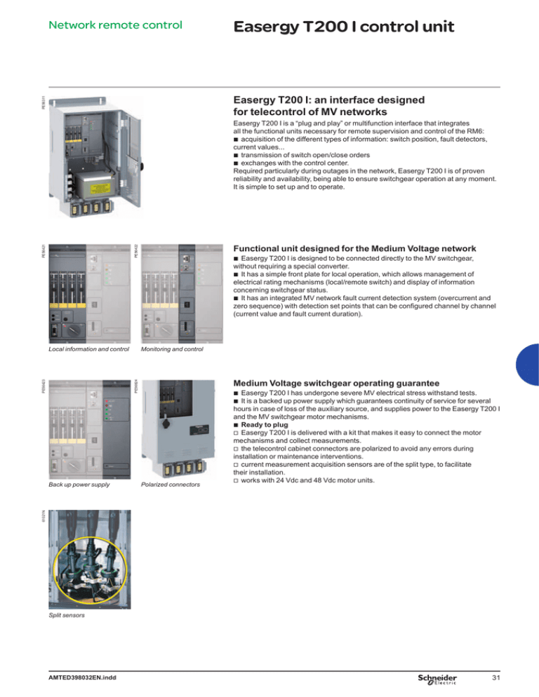
Network remote control Easergy T200 I control unit PE56311 Easergy T200 I: an interface designed for telecontrol of MV networks Functional unit designed for the Medium Voltage network PE56422 PE56421 Easergy T200 I is a “plug and play” or multifunction interface that integrates all the functional units necessary for remote supervision and control of the RM6: b acquisition of the different types of information: switch position, fault detectors, current values... b transmission of switch open/close orders b exchanges with the control center. Required particularly during outages in the network, Easergy T200 I is of proven reliability and availability, being able to ensure switchgear operation at any moment. It is simple to set up and to operate. Monitoring and control Medium Voltage switchgear operating guarantee PE56824 PE56423 Local information and control b Easergy T200 I is designed to be connected directly to the MV switchgear, without requiring a special converter. b It has a simple front plate for local operation, which allows management of electrical rating mechanisms (local/remote switch) and display of information concerning switchgear status. b It has an integrated MV network fault current detection system (overcurrent and zero sequence) with detection set points that can be configured channel by channel (current value and fault current duration). Polarized connectors 61021N Back up power supply b Easergy T200 I has undergone severe MV electrical stress withstand tests. b It is a backed up power supply which guarantees continuity of service for several hours in case of loss of the auxiliary source, and supplies power to the Easergy T200 I and the MV switchgear motor mechanisms. b Ready to plug v Easergy T200 I is delivered with a kit that makes it easy to connect the motor mechanisms and collect measurements. v the telecontrol cabinet connectors are polarized to avoid any errors during installation or maintenance interventions. v current measurement acquisition sensors are of the split type, to facilitate their installation. v works with 24 Vdc and 48 Vdc motor units. Split sensors AMTED398032EN.indd 31 Network remote control Automatic transfer system DE57986EN DE57988 Because a MV power supply interruption is unacceptable especially in critical applications, an automatic system is required for MV source transfer. For your peace of mind, RM6 gives automatic control and management of power sources in your Medium Voltage secondary distribution network with a short transfer time (less than 10 seconds), guaranteeing the hi-reliability of your installation. Vn SW2 voltage Auto changeover switch (ACO 1/2) SW1 voltage Changeover between two sources in the distribution network: SW1 and SW2. O Vn Operating modes O The operating mode is selected from the Easergy T200 I configurator. C SW1 T1 O T1 C SW2 O Line 1 SW1 Line 2 SW2 DE57985 MT10013EN Automatic control is performed by Easergy T200 I. This T200 I device can also be used for remote control with a wide range of modems and protocols. By default, the T200 I is provided with the RS232 modem and the Modbus/IP protocol. Semi-Auto mode, SW1 < > SW2 In the event of a voltage loss on one of the three phases of the active line, automatic control switches to the other channel after a time delay T1: opening of SW1 and then closing of SW2. Automatic control executes no return, except in case of voltage loss on the new active channel. Semi-auto operating mode Vn Semi-Auto mode SW1 > SW2, (SW2 > SW1) Automatic control executes only one changeover from channel 1 or 2 to the backup channel. SW1 voltage Mode Auto-SW1 or Auto-SW2 After a changeover, return to the priority channel occurs if the MV voltage on that channel is restored. O C O T1 SW1 C O SW2 T2 Auto-SW1 operating mode Configurable parameters: b Operating mode: semi-auto, auto SW1, auto SW2 b T1: 1 to 60 s in 1 s steps b T2: 10 to 60 s in 1 s steps b Automation system valid/invalid 32 AMTED398032EN.indd Automatic transfer system (cont.) DE56656EN Network remote control Bus tie coupling (BTA 2/3) SW2 voltage V2 Source changeover between 2 incoming lines (SW1 and SW2) and a busbar coupling switch (SW3). V1 SW1 voltage Operating modes O Standard Semi-Auto mode In the event of a voltage loss on one of the three phases of the SW1 line, following time delay T1, automatic control opens SW1 and then closes SW3. After closing of SW3, presence of voltage on SW2 is monitored for a period T3. If the voltage is lost during this period, SW3 opens and the system is locked. Same logic if the voltage disappears on SW2. F T1 O SW1 T3 F T2 SW3 O Auto mode Same sequence as Semi-Auto mode. Then, if the voltage returns normally on SW1 during a time delay T2, the system changes over (opening of SW3 and closing of SW1). Same logic if the voltage disappears on SW2. DE57977 Configurable parameters: b Operating mode b Automatic return SW1/SW2 b Automation system on/off b Delay before switching T1: 100 ms to 60 s in 100 ms steps b Delay before return T2: 5 s to 300 s in 1 s steps b Interlock delay on voltage loss T3: 100 ms to 3 s in 100 ms steps b Motorisation type: command time. SW1 SW3 “Normal” position SW2 SW1 SW3 SW2 Active coupling An ATS solution is made of: L2 DE57978 L1 VD3H VD3H T200 I M Voltage sensor: dedicated version of VPIS with voltage output signal. 2 VD3H Voltage detector: a relay is activated when a loss of voltage is detected from the VPIS voltage output signal. 2 FPI Fault Passage Indicator: if a fault current is detected, the Automatic Transfer System is locked in order to avoid closing the healthy line on the fault. 1 T200 I + switch function motorized From the digital input coming from the VD3H and the FPI information, T200 I takes the decision to switch from one line to the other. M SCADA AMTED398032EN.indd 2 VPIS-VO Communication to SCADA: optionally, communication facilities may be added. Modems: PSTN, Radio, GSM/GPRS, Ethernet,… Protocols: Modbus, IEC 870-5-101, DNP3,… Functions: dual port, remote configuration,… 33


