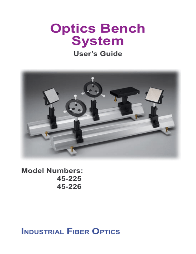
Optics Bench
System
User’s Guide
Model Numbers:
45-225
45-226
Industrial Fiber Optics
*
Copyright © 2009
by Industrial Fiber Optics, Inc.
Revision - E
Printed in the United States of America
*
*
*
All rights reserved. No part of this publication may be reproduced,
stored in a retrieval system, or transmitted in any form or by any means
(electronic, mechanical, photocopying, recording, or otherwise)
without prior written permission from Industrial Fiber Optics.
*
*
*
*
*
Introduction
This manual provides information about the Optics Bench System that was
formerly manufactured by Metrologic, Inc. It contains all the information needed
to assemble and set up the Optics Bench System, even if you are a novice to
optical technology. Please read the manual carefully before operating the Optics
Bench System.
As soon as you receive this Optics Bench System, inspect it and the shipping container for damage. If any damage is found, immediately refer to the section of this manual entitled Shipment Damage Claims.
Industrial Fiber Optics makes every effort to incorporate state-of-the-art technology, highest quality and dependability in its products. We constantly explore
new ideas and products to best serve the rapidly expanding needs of industry
and education. We encourage comments that you may have about our products,
and we welcome the opportunity to discuss new ideas that may better serve
your needs. For more information about our company and products refer to http//
www.i-fiberoptics.com on the Worldwide Web.
Thank you for selecting this Industrial Fiber Optics product. We hope it
meets your expectations and provides many hours of productive activity.
Sincerely,
The Industrial Fiber Optics Team
–i–
– ii –
TABLE OF CONTENTS
Introduction……………………….................…….....…………..……
i
USING THE OPTIC BENCH SYSTEM......…..........……..…...……..
1
General…………..............….............................……..…...……..
1
45-225 Optics Bench Parts List….............................................
2
45-290 Adjustable Mirror Holder................................................
3
45-122 Ring Mount...................................................................
3
45-212 Standard Pin Carriers....................................................
4
45-214 Heavy Duty Pin Carriers................................................
4
45-124 Mounting Pins...............................................................
4
45-208 Adjustable Laser Holder................................................
4
45-202 Standard Bench (.06 meters)........................................
5
45-201 Long Bench (1.0 meters)...............................................
5
45-221 Leveling Base Set (for .06 meter bench).......................
5
45-222 Leveling Base Set (for 1.0 meter bench).......................
5
WARRANTY.....................................................................................
6
SHIPMENT DAMAGE CLAIMS.......................................................
7
– iii –
USING THE OPTICS BENCH SYSTEM
General
Industrial Fiber Optics offers a research-grade optics bench system designed for economy
and interchangeability. For economy, we offer only the components that sell for the highest
value (hence, lowest cost). For interchangeability, components from most other optics
bench systems will fit on the ¼” – 20 TPI threads on the Industrial Fiber Optics mounting
pins.
Consider the system in four levels as diagrammed below:
Figure 1. Parts for the Optics Bench System
–1–
Figure 2. Assembled Optics Bench System
45-225 Optics Bench Parts List
#
QTY
PART #
DESCRIPTION
1*
2
45-202
0.6 Meter Benches
2*
1
45-221
Leveling Base Set for two 0.6 Meter Benches
3**
1
43-201
1.0 Meter Bench
4**
1
45-222
Leveling Base Set for 1.0 Meter Bench
5
4
45-212
Standard Pin Carriers with Pins
6
1
45-214
Heavy Duty Pin Carrier with Pin
7
3
45-124
Mounting Pins (purchased separately)
8
1
45-208
Adjustable Laser Holder
9
2
45-209
Adjustable Mirror Holders
10
2
45-122
Ring Mounts
* Included in 45-225
** Included in 45-226
Each component may be purchased separately.
–2–
45-209 Adjustable Mirror Holder
The mirror holder has a 75 mm square mounting plate, which rotates 360° around a horizontal axis. A 70 mm square front surface aluminized and overcoated mirror is supplied.
The mirror may be attached to the tilt plate if desired. Alternately, the tilt plate may be
drilled to various diameters to serve as a lens holder.
Parts
1 Tilt plate assembly: Consists of a 75 mm square aluminum plate attached to a
U-shaped bracket by the two thumb screws.
1 Front surface mirror: 70 mm square
1 Machine screw: ¼” – 20 x 3/8”
Assembly
Attach U-shaped bracket to the mounting pin by inserting ¼” – 20 machine screw
through the clearance hole in the U-shaped bracket and into the ¼” – 20 socket
on the mounting pin. The mirror may be attached to the tilt plate by peeling off the
backing on the adhesive.
45-122 Ring Mount
The ring mount has a 70 mm inside diameter and is intended for holding optical or
mechanical components up to 50 mm in diameter. Three cushioned thumb screws permit
precise positioning. When used in pairs, the ring mounts provide an excellent holder for
cylindrical lasers.
Part and Assembly
The ring mount is shipped fully assembled. Insert mounting pin into the ¼” – 20
socket on the ring assembly.
–3–
45-212 Standard Pin Carrier
45-214 Heavy Duty Pin Carrier
Each carrier fits on top of the triangular bench and may be locked in place with a thumb
screw. The standard pin carrier has one 30 mm base, good for close positioning. The heavy
duty pin carrier has a 60mm base, appropriate for supporting lasers and heavy objects. A 60
mm tall aluminum mounting pin is supplied with each pin carrier. The pins have ¼” – 20
male threads at one end and ¼” – 20 female threads at the other. Pins may be joined to
provide additional height.
Parts and Assembly
Pin carriers come fully assembled. Each consists of a carrier base with two thumb
screws and a mounting pin with a removable ¼” – 20 x 5/8” set screw.
45-124 Mounting Pins (set of three – may be purchased separately)
This is a set of three mounting pins, each 60 mm tall, which may be joined to the pins supplied with the pin carriers for extended height applications.
45-208 Adjustable Laser Holder
The Laser Holder has an 80 x 125 mm surface area, which tilts –10° to +30° from horizontal. A thumb screw provides fine adjustment for tilt. This holder can also serve as a leveling
table for prisms and other optical components.
Parts
1 Table assembly: Consists of a U-shaped mounting plate attached to a base
plate
1 Machine screw: ¼” – 20 x ¼”
1 Thumb screw:
¼” – 20 x 2”
Assembly
Screw mounting pin into the ¼” – 20 threaded hole in the center of the base plate.
Insert the thumb screw in the threaded hole at end of the base plate. Attach laser
by using ¼” – 20 machine screw through the clearance hole on tilt plate.
–4–
45-202 Standard Bench (0.6 meters)
45-201 Long Bench (1.0 meters)
Industrial Fiber Optics optics benches employ world-standard Zeiss Triangular design. The
benches are hollow aluminum extrusions guaranteed straight to within 1 mm per meter.
The base of the bench contains a threaded slot so that the bench can be connected to leveling bases or bolted directly to a table, if desired.
Parts (for each bench)
1 Bench
2 End plates
6 Screws: 6-32 x 5/16” self tapping
Assembly
Each end plate is fastened by inserting three screws through holes in the end plate
and into grooves in the bench extrusion.
If a heavyweight bench is desired, fasten one end plate, fill the hollow bench with
dry sand, and fasten the second end plate.
45-221 Leveling Base Set (for two 0.6 meter benches)
45-222 Leveling Base Set (for 1.0 meter bench)
When several triangular benches are being used, it is sometimes useful to level the individual benches. The Leveling Base Set consists of four bars (to level two benches) or two
bars (to level a single bench) and hardware.
Parts (for each bench)
2 Leveling bars: (approximately 25 x 175 mm)
4 Thumb screws: ¼” – 20 x 2”
2
Bolts: 3/8” x 16 x 7/8”
Assembly
Screw the thumb screws into the holes at the ends of each leveling bar. Attach the bar to the triangular bench by inserting the bolt through the bar into
the threaded channel at the base of the bench.
–5–
Warranty
The Industrial Fiber Optics 45-225 Optical Bench System is warranted against defects in
materials and workmanship for two years. The warranty will be voided if the Bench System
components have been damaged or mishandled by the buyer.
Industrial Fiber Optics’ warranty liability is limited to repair or replacement of any defective
unit at the company’s facilities, and does not include attendant or consequential damages.
Repair or replacement may be made only after failure analysis at the factory. Authorized
warranty repairs are made at no charge, and are guaranteed for the balance of the original
warranty.
Industrial Fiber Optics will pay the return freight and insurance charges for warranty repair
within the continental United States by United Parcel Service or Parcel Post. Any other
delivery means must be paid for by the customer.
The costs of return shipments for equipment no longer under warranty must be paid by the
customer. If an item is not under warranty, repairs will not be undertaken until the cost of
such repairs has been approved, in writing, by the customer. Typical repair costs range from
$75 - $250 and repairs usually take two to three weeks to complete.
When returning items for analysis and possible repair, please do the following:
•
In a letter, describe the problem, person whom we should contact, phone
number and return address.
•
Pack the unit and your letter carefully in a strong box with adequate packing material, to prevent damage in shipment.
•
Ship the package to:
ndustrial
Fiber Optics
1725 West 1st Street
Tempe, AZ 85281-7622
USA
If you would like to view our products on the Internet go to: www.i-fiberoptics.com
–6–
Shipment Damage Claims
If damage to an Industrial Fiber Optics product should occur during shipping, it is imperative that it be reported immediately, both to the carrier and the distributor or salesperson
from whom the item was purchased. DO NOT CONTACT INDUSTRIAL FIBER OPTICS.
Time is of the essence because damage claims submitted more than five days after delivery
may not be honored. If shipping damage has occurred during shipment, please do the following:
•
Make a note of the carrier company, the name of the carrier employee, the
date and the time of the delivery.
•
Keep all packing material.
•
In writing, describe the nature of damage to the product.
•
In cases of severe damage, do not attempt to use the product (including
attaching it to a power source).
•
Notify the carrier immediately of any damaged product.
•
Notify the distributor from whom the purchase was made.
------------------------------
–7–
Notes:
Notes:
12 0099
Rules for Laser Safety
•
Lasers produce a very intense beam of light. Treat them with respect. Most
educational lasers have an output of less than 3 milliwatts, and will not harm the
skin.
•
Never look into the laser aperture while the laser is turned on! PERMANENT
EYE DAMAGE COULD RESULT. •
Never stare into the oncoming beam. Never use magnifiers (such as binoculars or
telescopes) to look at the beam as it travels – or when it strikes a surface.
•
Never point a laser at anyone’s eyes or face, no matter how far away they are.
•
When using a laser in the classroom or laboratory, always use a beam stop, or
project the beam to areas, which people won’t enter or pass through. •
Never leave a laser unattended while it is turned on – and always unplug it when
it’s not actually being used. •
Remove all shiny objects from the area in which you will be working. This
includes rings, watches, metal bands, tools, and glass. Reflections from the beam
can be nearly as intense as the beam itself.
•
Never disassemble or try to adjust the laser’s internal components. Electric shock
could result.

