Overview Electrical Machines and Drives
advertisement

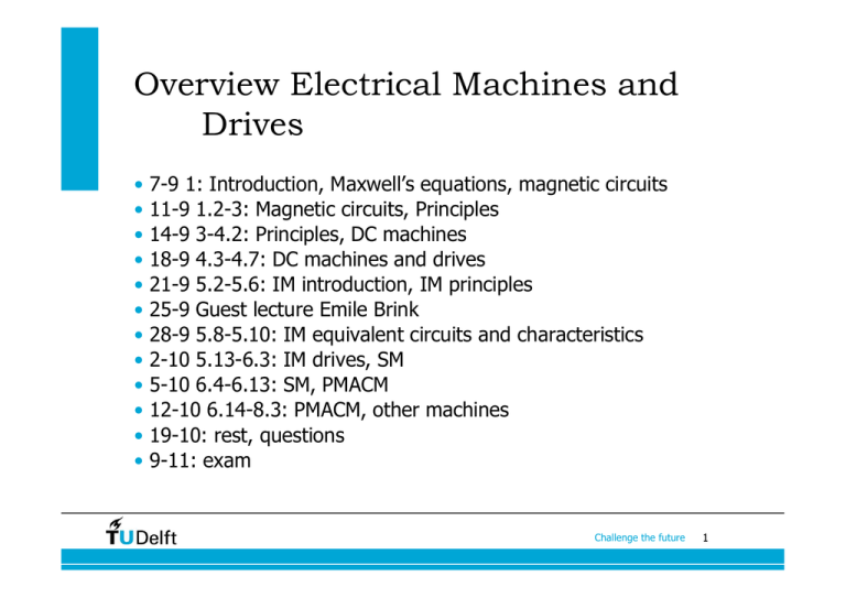
Overview Electrical Machines and Drives • • • • • • • • • • • • 7-9 1: Introduction, Maxwell’s equations, magnetic circuits 11-9 1.2-3: Magnetic circuits, Principles 14-9 3-4.2: Principles, DC machines 18-9 4.3-4.7: DC machines and drives 21-9 5.2-5.6: IM introduction, IM principles 25-9 Guest lecture Emile Brink 28-9 5.8-5.10: IM equivalent circuits and characteristics 2-10 5.13-6.3: IM drives, SM 5-10 6.4-6.13: SM, PMACM 12-10 6.14-8.3: PMACM, other machines 19-10: rest, questions 9-11: exam Challenge the future 1 DC Machines • Introduction, construction (4.2) • Principle of operation and basic calculations (4.2) • air gap flux density (1.1) • armature turn voltage and commutation (4.2.2) • armature windings (4.2.3) • total armature voltage (4.2.4) • torque (4.2.5) • magnetisation curve (4.2.6) • Armature reaction, interpoles, compensating winding (4.3) • Characteristics, means to control speed (4.4) • DC machine drives (4.5) • PMDC machines / PCB machines (4.6, 4.7) Challenge the future 2 Assumptions for calculations • steady state (mechanical and electrical) • the air gap is so small that the flux density does not change in radial direction • the air gap is so small that the flux density crosses the air gap perpendicular • iron losses are negligible • the magnetic permeability of iron is infinite Challenge the future 3 Air gap flux density • The field winding around one pole has Nf turns and carries a current If • Calculate the air gap flux density between the poles and the rotor Challenge the future 4 Flux density ∫ H ⋅τ d s = ∫∫ J ⋅ n d A Cm Sm 2H g lg = 2 N f I f Bg = µ0 N f I f lg Challenge the future 5 Flux density • Sketch flux linkage of a turn on the rotor • Calculate the maximum voltage induced in turn from Faraday’s law Challenge the future 6 Armature turn voltage At θ=0, the flux linkage is minimum dλ d et = = ∫∫ B ⋅ n d A d t d t Se d = −l dt θ +π ∫θ B(θ )r dθ dθ dθ − lrB(θ + π ) dt dt = 2lrB (θ )ω = 2lB(θ )v = lrB (θ ) Challenge the future 7 Commutator as rectifier Challenge the future 8 Commutation Commutating coil in interpolar region: no induced voltage Challenge the future 9 Armature windings • English: turn, coil, winding • Dutch: winding, spoel, wikkeling Challenge the future 10 Mechanical and electrical angles p θe = θm 2 p ωe = ωm 2 Challenge the future 11 DC Machines • Introduction, construction (4.2) • Principle of operation and basic calculations (4.2) • air gap flux density (1.1) • armature turn voltage and commutation (4.2.2) • armature windings (4.2.3) • total armature voltage (4.2.4) • torque (4.2.5) • magnetisation curve (4.2.6) • Armature reaction, interpoles, compensating winding (4.3) • Characteristics, means to control speed (4.4) • DC machine drives (4.5) • PMDC machines / PCB machines (4.6, 4.7) Challenge the future 12 Armature voltage An armature winding has N turns with a parallel paths and therefore N/a series-connected turns For the turn voltage, we found et = 2lrωm B(θ ) The average is lower: Flux per pole et = 2lrωm B (θ ) Φ = ∫∫ B ⋅ n d A = l 2π / p ∫ B(θ )r d θ = 0 Using this, the turn voltage is given by Therefore et = p π 2π rlB (θ ) p Φω m N Np Ea = et = Φω m = K a Φω m a πa Challenge the future 13 Voltage and torque from power balance d Ia U = RI a + L + K a Φ ωm dt d Ia 2 P = UI a = RI a + I a L + I a K a Φωm dt Power balance: P = P Cu + Pf + Pmech Therefore T= Pmech ωm = K a ΦI a Challenge the future 14 Electromagnetic torque from Lorenz Ia Fc = B(θ )lI c = B(θ )l a Ia Tc = rFc = B(θ )rl a Ia p Tc = B (θ )rl = ΦI a a 2πa Np T = 2 NTc = ΦI a = K a ΦI a πa P = ωmT = ωm K a ΦI a = Ea I a Lorenz force gives the same result as power balance. Challenge the future 15 Magnetic circuit Which part saturates first? Why? Challenge the future 16 Magnetization curve Why is this not a straight line? Why does it not start from zero? Challenge the future 17 DC Machines • • • • • • Introduction, construction (4.2) Principle of operation and basic calculations (4.2) Armature reaction, interpoles, compensating winding (4.3) Characteristics, means to control speed (4.4) DC machine drives (4.5) PMDC machines / PCB machines (4.6, 4.7) Challenge the future 18 Armature reaction • Section 4.3 (Sen) has the title “DC generators” • DC machines are hardly used as generators • The operating principles are the same in motoring and generating • Therefore, we only look at constructional aspects of DC machines discussed in 4.3, which are present in DC motors as well as in DC generators: • compensating winding (Dutch: compensatiewikkeling) • interpoles (Dutch: hulppolen) • Both are related to armature reaction Challenge the future 19 Armature reaction Challenge the future 20 Consequences armature reaction • Saturation • Commutation problems Challenge the future 21 Compensation winding • Saturation problem reduced • Expensive; only applied in machines that are often heavily loaded. Why in these machines? Challenge the future 22 Interpoles Armature reaction produces a flux density in the interpolar region, so that a voltage is induced in the commutating coil. This voltage opposes commutation. Interpoles reverse the direction of this flux density to induce a voltage that accelerates commutation. Challenge the future 23 DC Machines • • • • Introduction, construction (4.2) Principle of operation and basic calculations (4.2) Armature reaction, interpoles, compensating winding (4.3) Characteristics, means to control speed (4.4) • Connections of DC machines • Separately excited DC machine • Series connected DC machine • DC machine drives (4.5) • PMDC machines / PCB machines (4.6, 4.7) Challenge the future 24 Connections of DC machines Challenge the future 25 Separately excited DC machines Pole flux does not depend on armature voltage and load T = K a ΦI a Ea = ω m K a Φ U t = Ra I a + Ea Ra I a RaT U U ωm = − = − K a Φ K a Φ K a Φ ( K a Φ) 2 How to control speed? Calculate no-load speed and stall torque. Challenge the future 26 Torque speed characteristic • Where are motor, generator and plugging operation? • Speed control by means of • Voltage control: what happens if the voltage is increased? • Field control: what happens if the current is increased? • Resistance control: old-fashioned Challenge the future 27 Voltage control Challenge the future 28 Field control Are the characteristics of (c) parallel? Challenge the future 29 Series DC machine (universal motor) Φ = K1 I a T = K a ΦI a = K a K1 I a2 Neglecting saturation! What happens to the speed when the torque is zero? Challenge the future 30 Series DC motor Φ = K1 I a T = K a ΦI a = K a K1 I a2 U t = Ra I a + Ea = Ra I a + K a Φωm = Ra I a + K a K1 I aωm Ut Ia = Ra + K a K1ωm 2 U t T = K a ΦI a = K a K1 I a2 = K a K1 ( Ra + K a K1ωm ) 2 Ut Ra ωm = ± − K a K1T K a K1 Challenge the future 31 DC machines • • • • • Introduction, construction (4.2) Principle of operation and basic calculations (4.2) Armature reaction, interpoles, compensating winding (4.3) Characteristics, means to control speed (4.4) DC machine drives (4.5) • Ward-Leonard system • Power electronics (Rectifier, Chopper) • Closed loop control • PMDC machines / PCB machines (4.6, 4.7) Challenge the future 32 Overview Electrical Machines and Drives • • • • • • • • • • • • 7-9 1: Introduction, Maxwell’s equations, magnetic circuits 11-9 1.2-3: Magnetic circuits, Principles 14-9 3-4.2: Principles, DC machines 18-9 4.3-4.7: DC machines and drives 21-9 5.2-5.6: IM introduction, IM principles 25-9 Guest lecture Emile Brink 28-9 5.8-5.10: IM equivalent circuits and characteristics 2-10 5.13-6.3: IM drives, SM 5-10 6.4-6.13: SM, PMACM 12-10 6.14-8.3: PMACM, other machines 19-10: rest, questions 9-11: exam Challenge the future 33


