5. energy conversion Week 15 ALIGNMENT FORCE AND TORQUE: SINGLE EXCITATION
advertisement
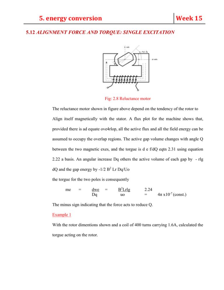
5. energy conversion Week 15 5.12 ALIGNMENT FORCE AND TORQUE: SINGLE EXCITATION Fig: 2.8 Reluctance motor The reluctance motor shown in figure above depend on the tendency of the rotor to Align itself magnetically with the stator. A flux plot for the machine shows that, provided there is ad equate ove4rlop, all the active flux and all the field energy can be assumed to occupy the overlap regions. The active gap volume changes with angle Q between the two magnetic exes, and the torgue is d e f/dQ eqtn 2.31 using equation 2.22 a basis. An angular increase Dq others the active volume of each gap by - rlg dQ and the gap energy by -1/2 B2 Lr Dq/Uo the torgue for the two poles is consequently me = dwe Dq = B2Lrlg uo 2.24 = 4π x10-7 (const.) The minus sign indicating that the force acts to reduce Q. Example 1 With the rotor dimentions shown and a coil of 400 turns carrying 1.6A, calculated the torgue acting on the rotor. 5. energy conversion Week 15 Solution The mmf (F) = NI 400 X 1.6 Area fine B =UOH Then F = 640 :. = 640 A.t HX 21g => BX2lg Uo B =640 x UO 2lg 640 X 4π X 190-7 2 x 10-3 = 0.40 tesla 0.43 i.e The flux density in each 1mm gap B = 0.40T. :. me = -0.42 X 0.025 X0.03 X0.001 X107 = 0.0955N-M -B2l/g4 π Example 2 The 4-l characteristics of a magnetic circuit are frequently described with straight segments as shown below. The act is considered linear up to pt. a and in saturation from a to 5 find the field energy Example 3 A dynamic phonograph pickup consists of a 20-turn coil length of each coil =1cm) moving normal to a field of B=0.2t. if the maximum allowable amplitude is 0.02mm, calculated the output voltage at 100-HZ and at 100Hz Solution 5. energy conversion Week 15 A dynamic phonograph pickup for vertical recording the effective conductor in moving coil is L = 20turns =20cm =0.2m For a sinusoidal displacement of amplitude 2 x 10⁻⁵ m =0.02mm X (t) =Asinwt = 2x 10⁻⁵ sinwt The velocity at 100HZ is d x /dt or U =dx =2 x10-5 x 2π x 103conwt m/s. Neglecting internal impedance, the output voltage is V = e =Blu =0.2 x 0.2 x 4π x 10-2 coswt colt The r.m.s value of output voltage is V = vmax = 0.2 x0.2 x 4 π x10-2 2 2 = 0.0036v =3.6mv (ii) The velocity at 100HZ is U = dx =2 x 100-5 x 2 π x 102 coswt m/s And output voltage (neglecting internal impedance) is V =e bLu = 0.2 x 0.2 4 π x 10-3 coswt volt And r.m.s value of output voltage = 0.2 x 0.2 x 4 π x 10-3 2 = 0.00036v =0.36mv length of 5. energy conversion Week 15 Example4. In a d.c machine, shown above, the armature is wound on a laminated iron cylinder 15cm long and 15cm in diameter. The N and S role faces are 15cm long (into the paper) and 10cm along the circumference the average flux density in the air gap under the pole faces is 1T. If there are 80 conductors in series between the brushes and the machine turning at N =1500rpm, calculated the no-load terminal voltage Solution For Ns conductor (no coils) in series, the average emf is E =NS ∆Ø wb =Ns Ø wb P poles ∆t s pole rev = Ns Øpn n 60 rev sec No 2 conductor in sec) volts Where the flux per pole Ø = BA = 1 x0. 15 x 0.1 = 0.015 wb. :. Example 5. E = 80 x 0.015 x 2 x 1500 60 = 60 volts 5. energy conversion Week 15 A magnetic circuit is completed through a soft –iron rotor as shown in the figure above. Assuming (1) all the reluctance of the magnetic circuit is in the air gaps of length L (ii) There is no fringing so the effective area of each gap is the area Derive on expression for the torgue as a function of angular position. Solution The total reluctance for two air gaps in series is R = 2l UOA (since Ur =1 for air) R = F =1L Q A = 2L Urwq For an N-turn coil, the inductance is L = NØ = NF N2I I IR IR = N2 trwØ 2L Since torgue =1/2 I2 dL = Uo N2rw dØ 2L The torgue is independent of Ø under the assume conditions. Example 6 (a) Wiring diagram (b)Steady state model A commutator machine, with the wiring diagram and steady-state model showed above, is rated 5KW , 250V, 2000rmp. The armature resistance RA is 1. Drive from the electrical and at 2000rmp, the no-load powder input to the armature is IA = 1.2A at 250V with the field winding (RE =250) excited by IF =1A. Calculate the efficiency of this machine. 5. energy conversion Week 15 Solution In fig (a), input power IF 2RF = 12 X 250 =250W is required to provide the necessary magnetic flux. This is power lost and it appears as heat. In no-load steady operation, there is no output and no change is all loss [The armature cooper loss at no load is negligible (1.22 x 1=1.44w) and most of the input power at no- load goes to supply air, bearing brush friction, eddy cumenty and hystersis losses] the losses are associated with flux changes in the rotting armature core, are dependent on speed but are nearly independent of load. Hence, field loss = IF2RF = 250W IAV = At full-load of 5KW, IA =5000W = 20A And the armature copper loss = IA2 Ra =202 x1 =400w And rotational loss = 300w p =iv :.i = p1 v The energy balance equation gives Mech. Energy :input + field elect input output = increase energy Field energy stored converted to heat i.e Mech. input + 250-5000 = 0 field arm less less rotat less Mech. input + 250 -5000 = 0 + 250 +300 + 400 (field input is all loss and appears o n both sides) Mech. Input = 500 + 300 + 400 =5700W. Hence efficiency = output Input = elect output mech. output + elect input = 5000 5700 + 250 = 0.84. or 84% 5. energy conversion Week 15 Example 7 In the relay shown above, the contacts are held open by the spring excerting a force of 0.1N . The gap length is 4mm when the contacts are open and 1mm when closed. The coil of 5000 turns would on core 1cm2 in cross- section. Assuming 1) All reluctance is in a uniform air gap


